Proportional pressure control valve

a technology of proportional pressure control and valve body, which is applied in the direction of valve housing, fluid pressure control, instruments, etc., can solve the problems of affecting the starting behavior of the vehicle, perceived unpleasantness, and the response behavior of the transmission shift clutch is correspondingly delayed, so as to reduce the flow resistance and reduce the effect of dynamic regulation capability and short response tim

Active Publication Date: 2009-04-14
ZF FRIEDRICHSHAFEN AG
View PDF21 Cites 19 Cited by
  • Summary
  • Abstract
  • Description
  • Claims
  • Application Information

AI Technical Summary

Benefits of technology

[0014]The proportional, pressure control valve constructed, according to the invention, has the advantage of a lower flow resistance compared with customary pressure control valves and ensures an increase in the dynamic regulation capability of the power shifting clutches, which are starting clutches in automatic transmissions without hydrodynamic starting element or gearshifting clutches. It also has the advantage of shorter response times and results in an increase in the cut-off frequency of the system of clutch+start element, so that at minus temperatures a spontaneous frictional connection is possible.

Problems solved by technology

The energy requirement for this component part is especially high with cold transmission oil, which affects the starting behavior of the vehicle.
In addition, the response behavior of the transmission shift clutches is correspondingly delayed in the minus temperature range, which is also perceived to be unpleasant.

Method used


Image

  • Proportional pressure control valve
  • Proportional pressure control valve
  • Proportional pressure control valve

Examples


Embodiment Construction

[0018]Such proportional, pressure control valves are well known in the art, so that in the following only those parts are described, which are needed for an understanding of the invention.

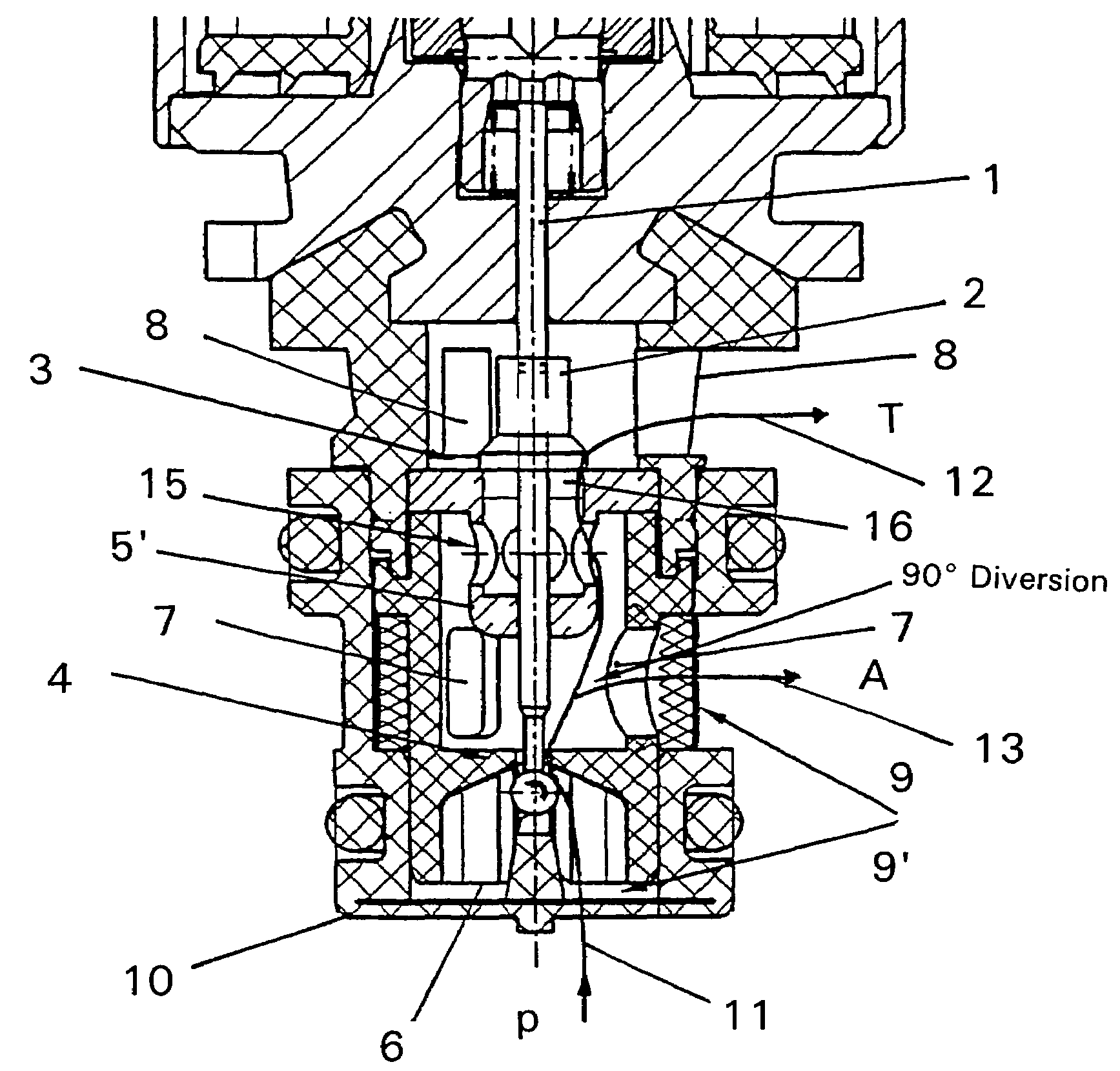
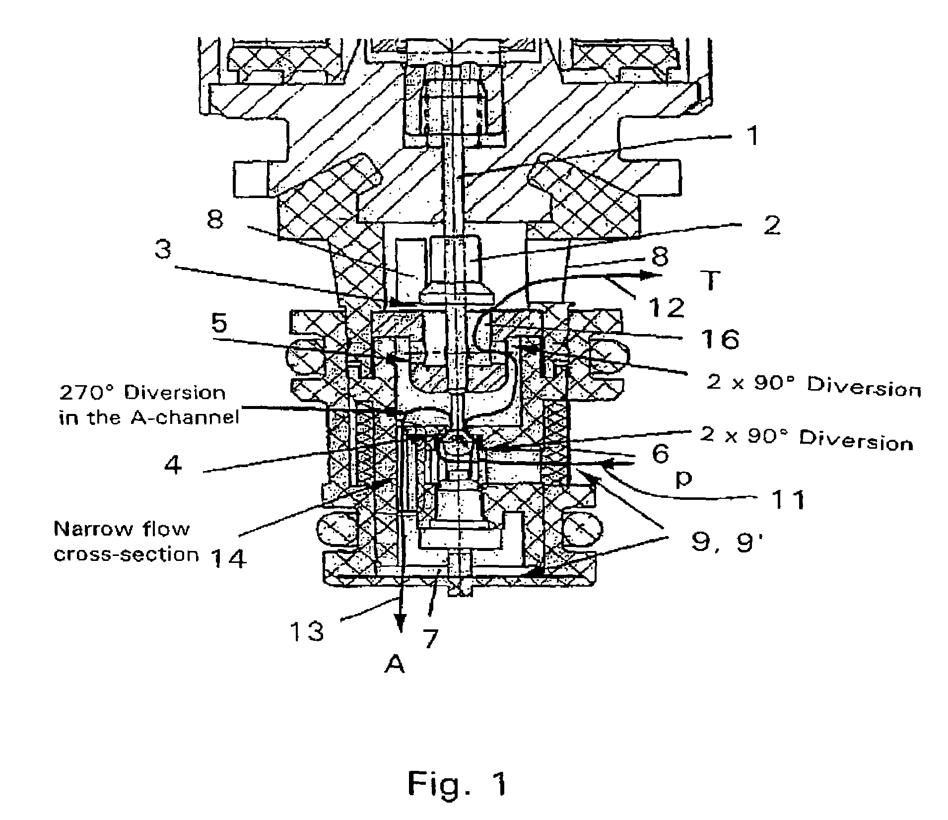
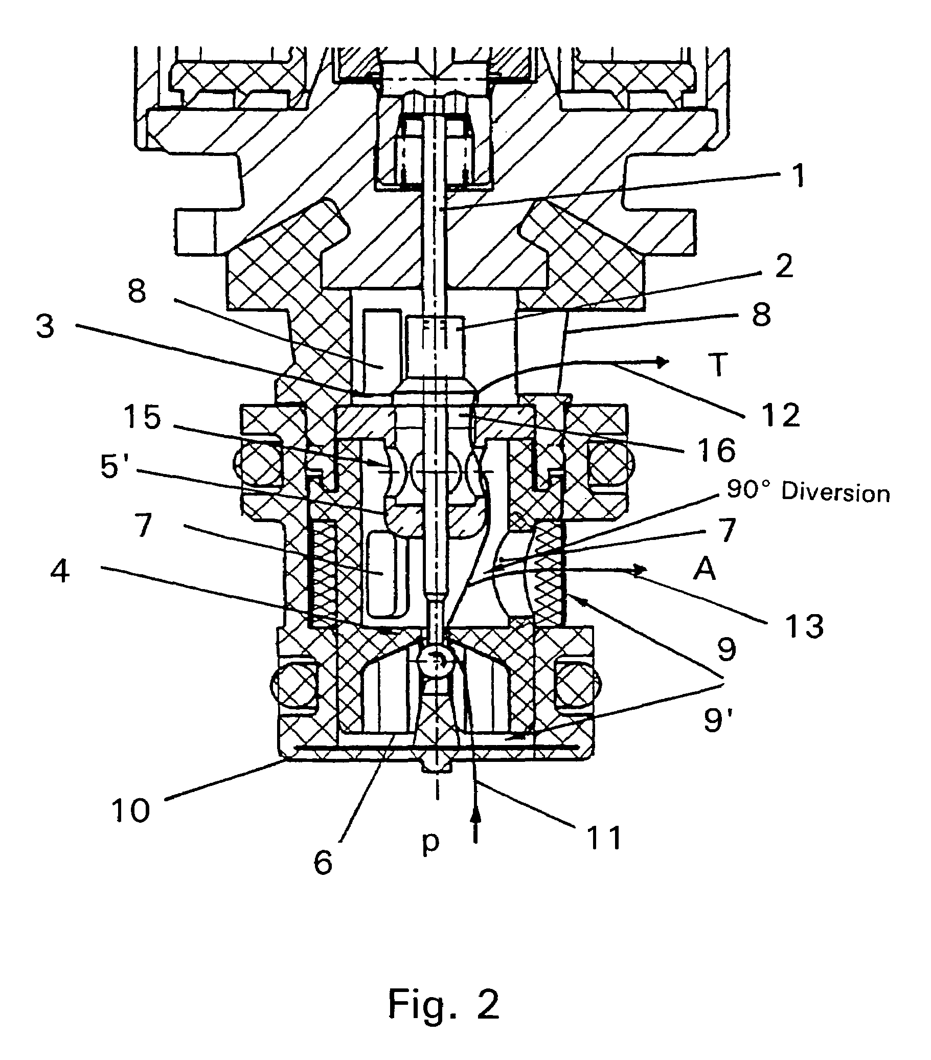
[0019]The proportional, pressure control valve comprises a magnetic part shown without detail in the upper part of FIG. 1, which part comprises the customary magnetic core, a magnetic coil and a movable armature, as well as a movable activation part 1 of the armature for a closing part 2, which can come to a stop on a flat seat 3 and thereby closes a continuous opening 16 incorporated in the flat seat.

[0020]Number 4 designates a customary ball seat for a valve; 5 designates a stream diverter; 6 designates an inflow opening for an inflow volume stream with an inflow pressure p; 7 designates an outflow opening for the filling volume stream to the clutch with the operating pressure A; 8 designates an outflow opening for the tank volume stream with the ambient pressure T; 9 and 9′ designate two, small ...


PUM


Abstract

Proportional pressure control valve with a magnetic part and a valve part, the valve part has an inflow opening for the inflow stream, a first outflow opening for the filling stream, and a second outflow opening for the tank volume stream, and has a ball seat, a flat seat with an opening, a closing part for controlling the throughput quantity through the opening of the flat seat, and a stream diverter. The inflow opening faces away from the magnetic part and coaxially to its longitudinal axis, and the outflow openings are constructed on the side wall of the valve part radially to its longitudinal axis, so that fluid flowing from through the valve is exposed to a diversion of a maximum of 90°. The fluid, after flowing through the ball seat and to and through the stream diverter, experiences a diversion of less than 30°.

Description

[0001]This application is a national stage completion of PCT / EP2004 / 009289 filed Aug. 19, 2004 which claims priority from German Application Serial No. 103 42 892.5 filed Sep. 17, 2003.FIELD OF THE INVENTION[0002]The present invention relates to a proportional pressure control valve for regulating the pressure level in a hydraulic circuit.BACKGROUND OF THE INVENTION[0003]According to the state of technology, the pressure in a transmission, especially in an automatic transmission for motor vehicles, is regulated in a hydraulic circuit based on demand. While the pressure level in the hydraulic circuit can be kept low for the lubricating oil supply of the transmission parts. The pressure must be greatly increased during the shifting process in order, for example, to be able to quickly fill the shift elements.[0004]Normally for the regulation of pressure in hydraulic circuits, pressure regulators are used, which control slides for clutch activation. The control of the slides occurs with...

Claims


Application Information

Patent Timeline
Patent Type & Authority Patents(United States)
IPC IPC(8): F15B13/044G05D16/20
CPCF16D48/02F16K27/0263F16K31/0603G05D16/2013F16K27/029F16D2048/0221G05D16/2024Y10T137/87217Y10T137/86678F16K31/06G05D16/20
Inventor MAYR, KARLHEINZSCHMIDT, THILOKILL, WALTERMOOSMANN, MARKUS
Owner ZF FRIEDRICHSHAFEN AG
Why Eureka
Try Eureka