Method and apparatus for improving AC transmission system dispatchability, system stability, and power flow controllability using DC transmission systems

a transmission system and transmission system technology, applied in non-electric variable control, process and machine control, instruments, etc., can solve the problems of power stability and service interruption, cost of small generators, and difficulty in populated areas to sit them

Inactive Publication Date: 2009-04-14
ELECTRIC POWER RES INST INC
View PDF6 Cites 59 Cited by
  • Summary
  • Abstract
  • Description
  • Claims
  • Application Information

AI Technical Summary

Benefits of technology

[0005]According to another embodiment of the invention, a plurality of isolating DC-DC converters is interposed at predetermined locations on the DC transmission ring for isolating faults on the DC transmission ring to prevent the faults from disturbing the system or causing complete system collapse.

Problems solved by technology

This arrangement is vulnerable to voltage stability and service interruptions due to outage or fault events on one or more of the long distance lines serving the area, which subsequently cascade into the local area.
Additionally, it is difficult to control the loading of either the long distance lines or the local network.
Typically this would require the addition of expensive AC controllers such as the Unified Power Flow Controller (UPFC) or other flexible AC transmission systems (FACTS) devices.
However, such a solution has many difficulties, including the cost of small generators and the difficulty siting them in populated areas.
Moreover, this solution does not provide for the wheeling of bulk power through the area.

Method used


Image

  • Method and apparatus for improving AC transmission system dispatchability, system stability, and power flow controllability using DC transmission systems
  • Method and apparatus for improving AC transmission system dispatchability, system stability, and power flow controllability using DC transmission systems
  • Method and apparatus for improving AC transmission system dispatchability, system stability, and power flow controllability using DC transmission systems

Examples


Embodiment Construction

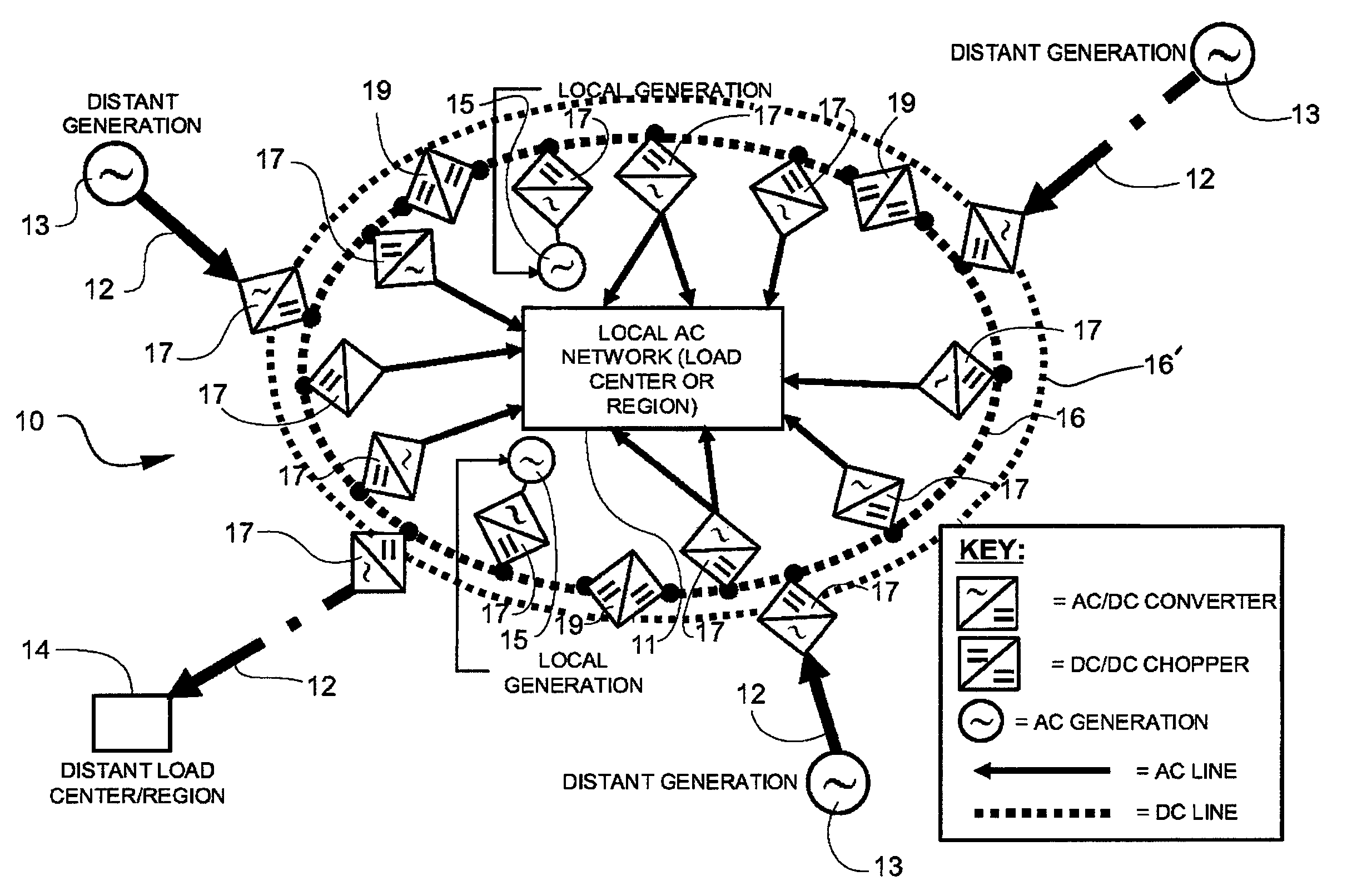
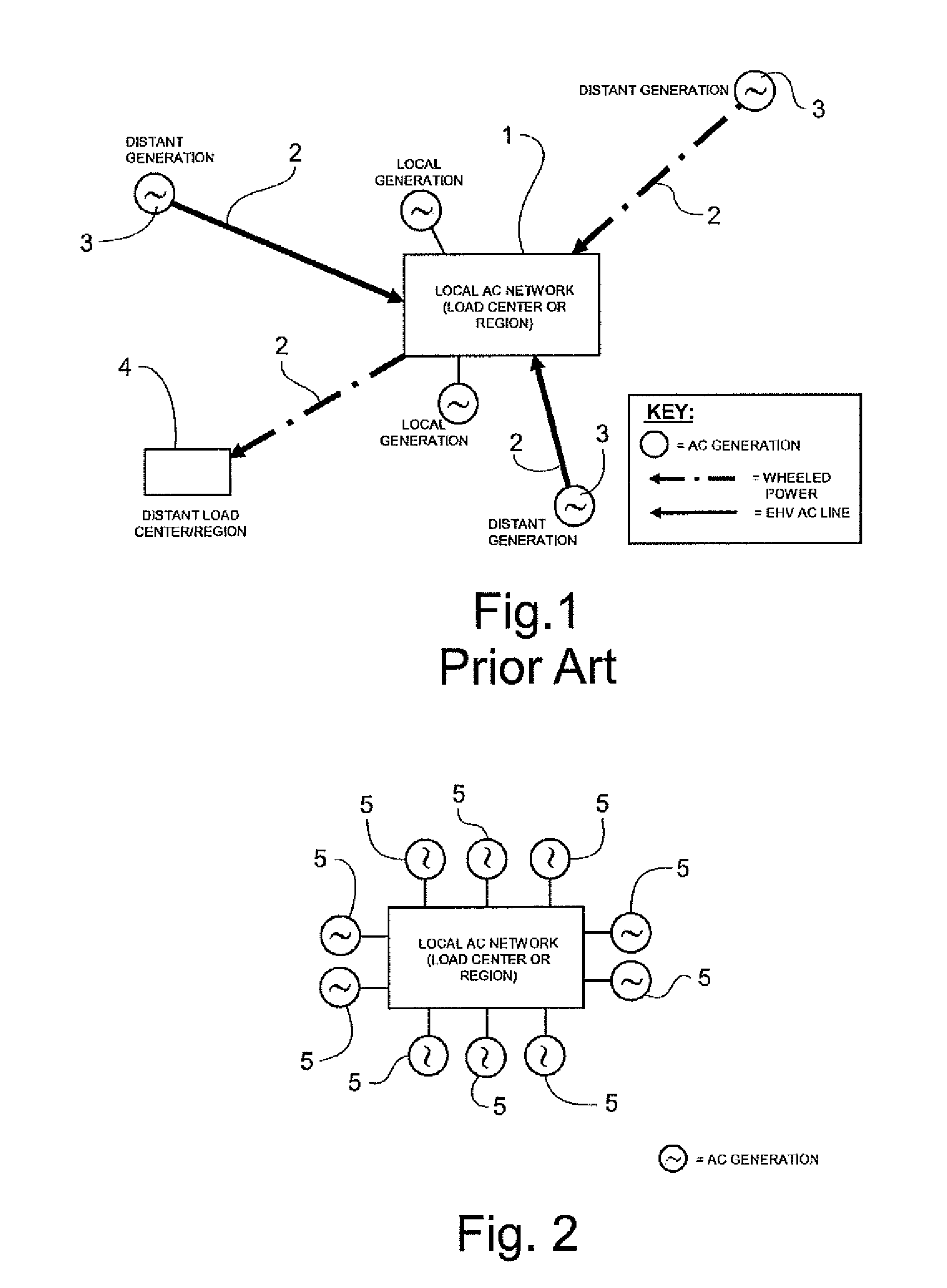
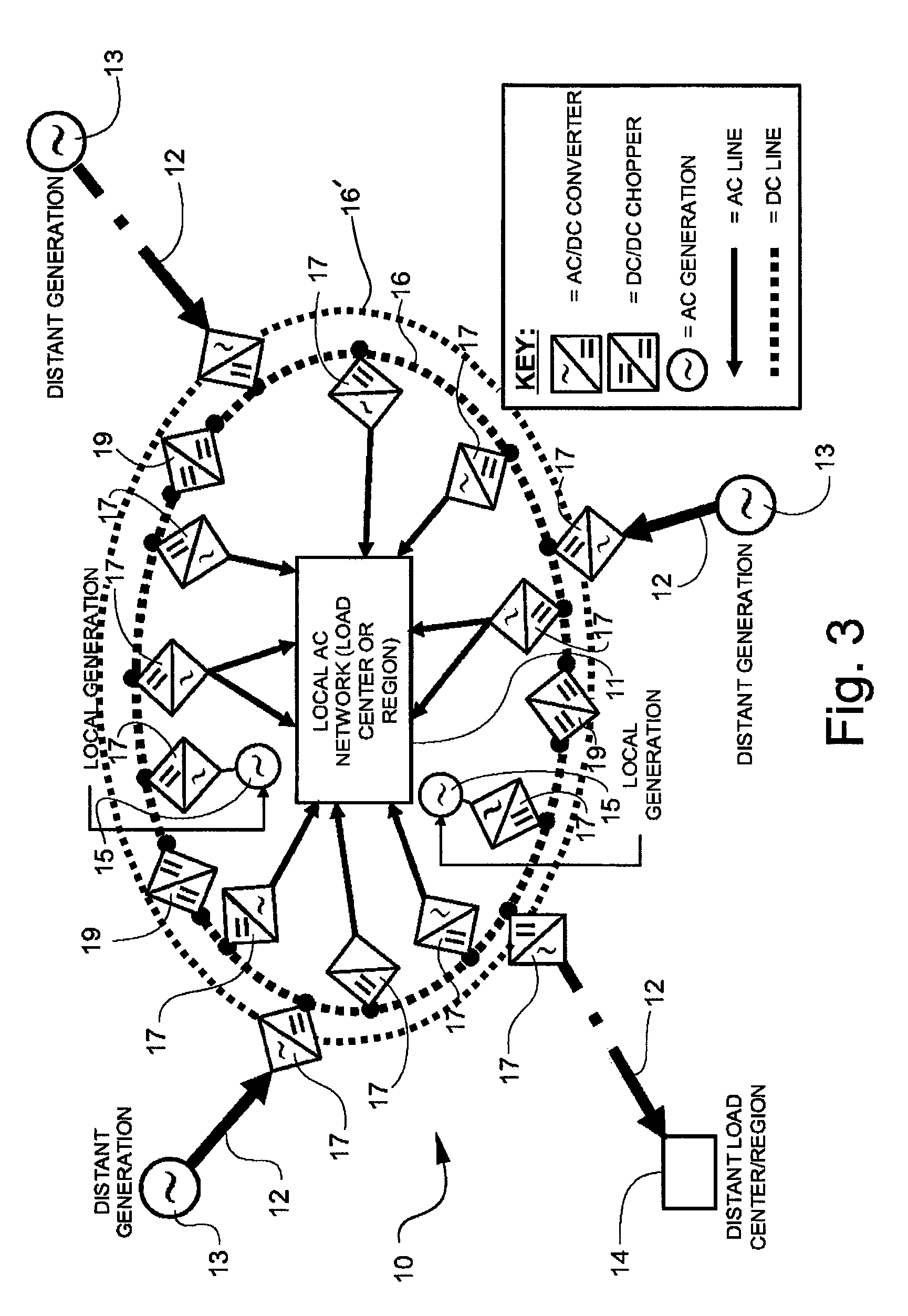
[0030]As referenced above, FIG. 1 depicts a typical AC network that includes a local AC load center or region, 1, fed or traversed by several high voltage (HV) or extra-high voltage (EHV) AC transmission lines, 2. Distant generation stations 3 (e.g., nuclear or coal-fired), generate electricity that is either consumed in the local AC load center or wheeled through the local AC load center to more distant markets 4. Nearby or “local” generating stations 5 also provide electricity to local and / or distant markets. Power flow in this local and extended AC network is regulated by Ohm's Law—that is, it is not actively controlled. Power flows to the path of least resistance, potentially leading to under-utilized and / or over-loaded transmission and distribution assets. Faults on the HV or EHV feeders may cascade into the local AC transmission network leading to outages. Voltage instabilities or collapse may occur in the local AC transmission network due to unregulated flow through the netwo...


PUM


Abstract

An electric power transmission system that isolates a local AC transmission network from a surrounding AC system includes a local AC load center having a plurality of local AC loads, and a distribution feeder serving the plurality of local AC loads and at least one distant electric power generating station or other power source for supplying AC power to the local AC load center. A complete or partial DC transmission ring is interposed between the local AC load center and the distant electric power generating station for isolating the AC power received from the distant electric power generating station from the local AC load center by converting the AC power to DC power. The DC power is re-converted into AC power based on load requirements and the distribution feeder supplies the AC power while all local AC loads are isolated from the distant electric power generating station.

Description

TECHNICAL FIELD AND BACKGROUND OF THE INVENTION[0001]This invention relates to a method and apparatus for improving AC transmission system dispatchability, system stability, and power flow controllability using DC transmission systems. Consolidated load centers (e.g., large urban areas or geographical areas with significant contiguous load) are typically served through a local AC network by a combination of local generation (i.e., inside or immediately adjacent to the load center) and long distance, high-voltage AC or DC transmission lines from distant generation sources. Often, the area is enclosed or partially enclosed by a high voltage AC ring. In some cases, power destined for other, distant load centers is fed, or “wheeled” through the local AC network. This is illustrated schematically in FIG. 1. This arrangement is vulnerable to voltage stability and service interruptions due to outage or fault events on one or more of the long distance lines serving the area, which subsequen...

Claims


Application Information

Patent Timeline
Patent Type & Authority Patents(United States)
IPC IPC(8): H02J3/38G05D9/00H02J1/00H02J3/00
CPCH02J3/02H02J11/00
Inventor ECKROAD, STEVEN WALLACE
Owner ELECTRIC POWER RES INST INC
Why Eureka
Try Eureka