Method and device for commutating electromechanical actuators

Active Publication Date: 2009-04-14
JOHNSON ELECTRIC INTERNATIONAL AG
View PDF8 Cites 10 Cited by
  • Summary
  • Abstract
  • Description
  • Claims
  • Application Information

AI Technical Summary

Benefits of technology

[0009]The teaching of the invention is explained in more detail hereinafter by means of a preferred exemplary embodiment and with reference to the figures. In the description of FIGS. 1-6, a method is presented that allows a particularly simple detection of the zero crossover of the back EMF voltage. The commutation of the motor winding preferably occurs near this zero crossover of the back EMF voltage and

Problems solved by technology

These methods are very demanding and therefore associated with high costs: The motor voltages and currents have to be measured, the parameters of the motor must be known (i.e. they have to be measured before for each motor type or estimated i

Method used


Image

  • Method and device for commutating electromechanical actuators
  • Method and device for commutating electromechanical actuators
  • Method and device for commutating electromechanical actuators

Examples


Embodiment Construction

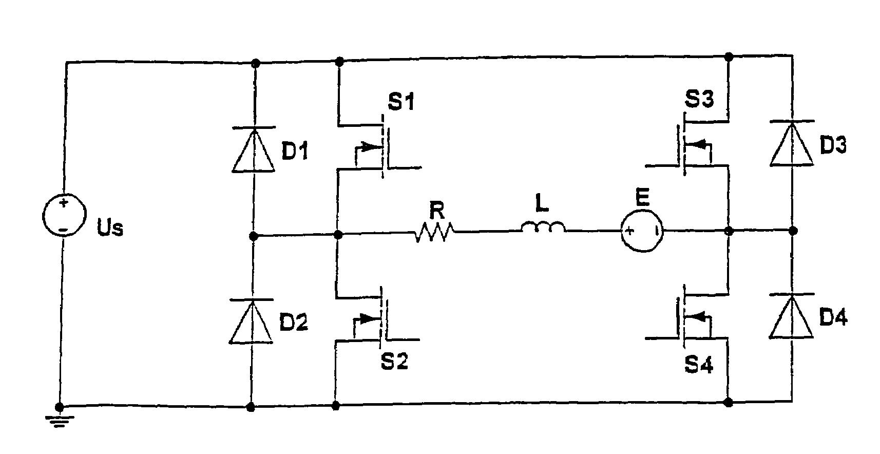
[0024]FIG. 1 shows the circuit diagram of a motor winding controlled by a bipolar driver. The motor winding is modeled by winding resistance R, winding inductance L, and by a back EMF voltage source E. The back EMF voltage is induced by the variation of the magnetic flux of the rotor. It is generally sinusoidal or trapezoidal.

[0025]The motor winding is controlled by a switched driver. In the present example, the latter is a H-bridge or a bipolar driver, but the method can also be implemented using an unipolar driver or any other driver topology.

[0026]The H-bridge comprises four switching transistors S1-S4 by which the motor winding is connectable to a supply voltage US. In parallel to switching transistors S1-S4, recovery diodes D1-D4 are provided. When switching transistors S1 and S4 (or S3 and S2, respectively) are switched on, a current flows from US through R, L, and E. This current is measured in a switching transistor or in a an additional measuring resistor (shunt), which is ...


PUM


Abstract

The invention relates to the commutation of electromechanical, commutatorless actuators, more particularly of permanent magnet motors and reluctance motors, having a rotor and a stator including at least one stator winding (W1, W2) that is/are operated with a constant current (IPWM). The method for determining the moment of commutation used herein comprises the following steps: A reference constant current is applied to at least one of the windings (W1, W2) and a stationary state is awaited. Then, a value that represents the voltage applied to the winding of the actuator in the stationary state is determined as the reference commutation value for the commutation voltage. While the motor is running, the commutation (if the motor is being operated with the reference current) is performed as soon as the reference value appears or a specified time later.

Description

CROSS-REFERENCE TO RELATED APPLICATION[0001]This application is the National Phase of PCT / CH2005 / 000020, filed Jan. 17, 2005, and published as WO 2005 / 069480, which in turn claims priority from PCT / CH2004 / 000028, filed Jan. 19, 2004, and published as WO 2005 / 069479, the contents of which are hereby incorporated by reference.BACKGROUND OF THE INVENTION[0002]The invention relates to a method for commutating electromechanical, commutatorless actuators, more particularly of permanent magnet motors and reluctance motors, having a rotor and a stator including at least one stator winding (W1, W2) that is / are operated with a constant current (I), and to a device for implementing the method.[0003]Brushless electric motors (more generally: electromechanical, or more precisely electromagnetic actuators) have electronic switches (e.g. transistors) instead of so-called brushes (mechanical contacts). These switches serve to electronically commutate the motor, i.e. they determine the direction of ...

Claims


Application Information

Patent Timeline
IPC IPC(8): H02H7/09H02P6/18
CPCH02P6/182
Inventor BALSIGER, WERNER
Owner JOHNSON ELECTRIC INTERNATIONAL AG
Why Eureka
Try Eureka