Micro-Fluidic Particle Concentrator and Filtering Device

a technology of microfluidic particles and filtering devices, which is applied in the field of microfluidics and microfluidic devices, can solve the problems of mass cell loss in dead volume, difficult manipulation of solutions containing high cell densities, and still lacking critical functions essential to mimic the anatomy of organs

Pending Publication Date: 2021-12-23
ECOLE POLYTECHNIQUE FEDERALE DE LAUSANNE (EPFL)
View PDF1 Cites 0 Cited by
  • Summary
  • Abstract
  • Description
  • Claims
  • Application Information

AI Technical Summary

Benefits of technology

[0006]In order to address and overcome the shortcomings of the prior art, the inventor created an optimized microfluidic device that acts as a crossflow particle concentrator and / or purifier, with a particular focus on a novel approach to bring cell concentration functionality to the printing heads of an extrusion-based bio-printer. One of the aspects of the present invention is to provide for a simple and efficient method and device to concentrate particles, particularly cells, in an interface easily adaptable to external devices such as Fluorescence-activated cell sorters (FACS) or 3D bio-printers.
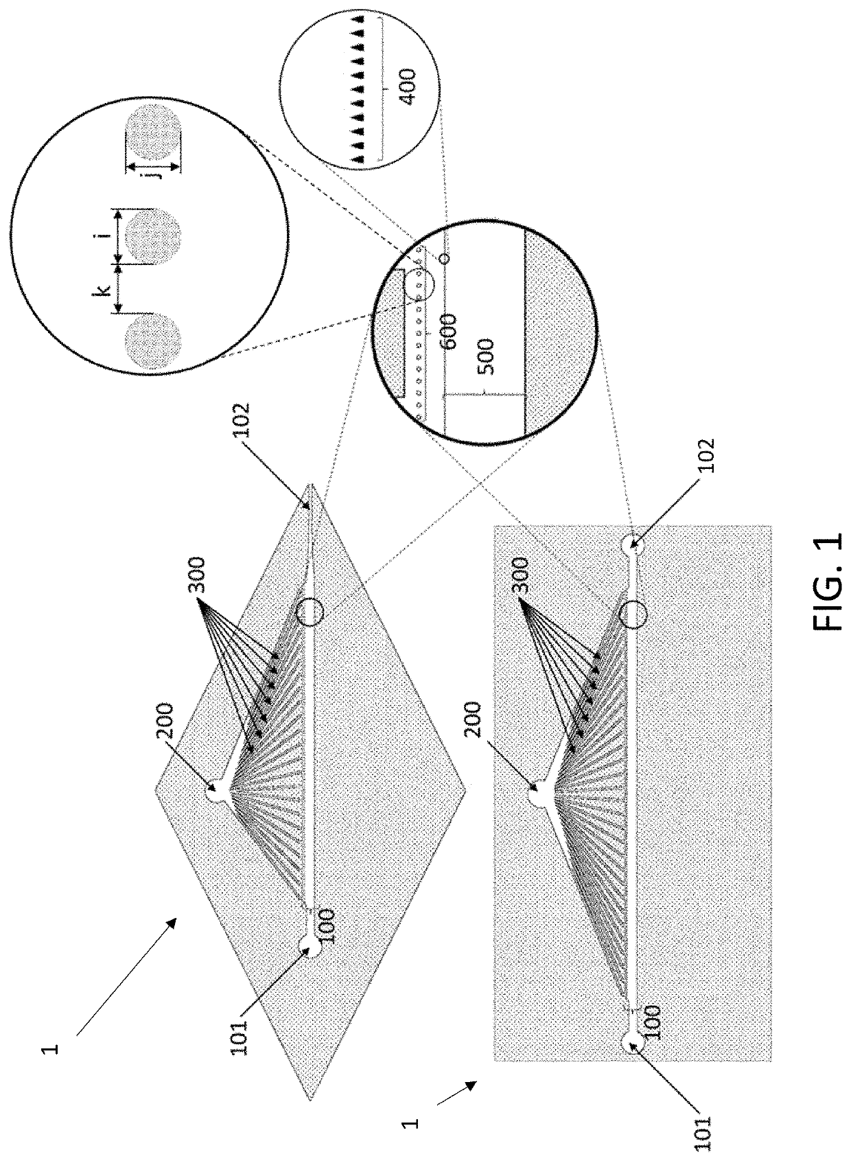
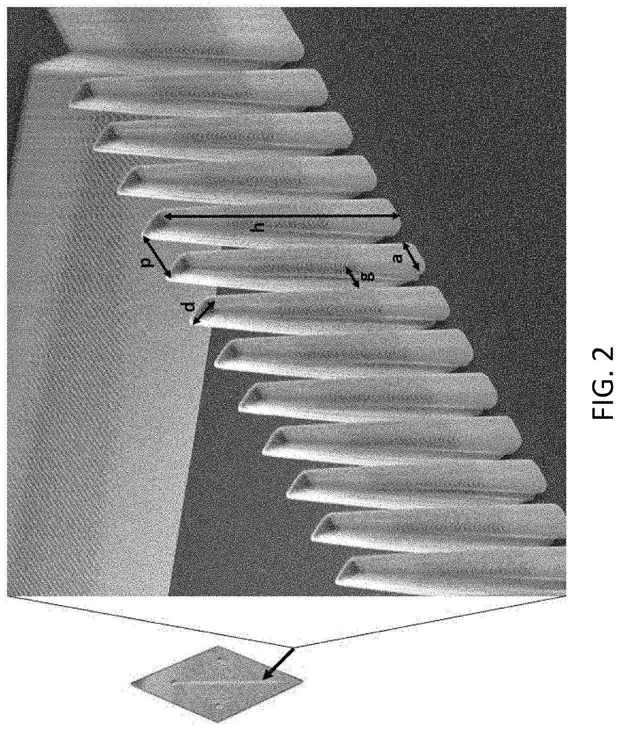
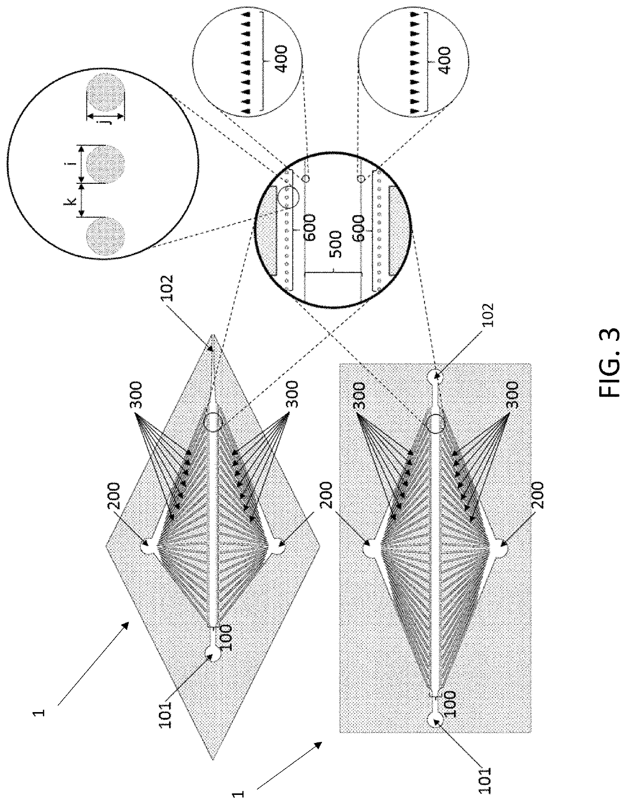
[0008]All those aims have been accomplished through the microfluidic device, presented herein, as described hereinafter. In an implemented embodiment, the microfluidic device features a flow channel into which particles to be collected converge from an inlet to an outlet in such a way that a concentration gradient forms along the channel, due to the action of pressure / flow means connected thereon. This is obtained thanks to two parallel rows of pillars of different shapes and distribution acting on the optimization of the particles' flow into the channel and a crossflow providing a tangential filtration. The microfluidic device has been successfully used as an interface between a particles' (cells) source and a bio-printer, allowing a much more efficient production of a cell-loaded biomaterial for tissue engineering.

Problems solved by technology

However, even though bio-printers have undergone improvements, the dispensing methods still lack critical functionalities essential to mimic the anatomy of organs.
However the manipulation of solutions containing high cell densities can be challenging especially in the context of 3D printing.
Conveying high cell density solutions through those tubing would lead to massive cell loss in dead volume as well as reduced viability because of cell lysis.

Method used


Image

  • Micro-Fluidic Particle Concentrator and Filtering Device
  • Micro-Fluidic Particle Concentrator and Filtering Device
  • Micro-Fluidic Particle Concentrator and Filtering Device

Examples


Embodiment Construction

[0042]The present disclosure may be more readily understood by reference to the following detailed description presented in connection with the accompanying figures, which form a part of this disclosure. It is to be understood that this disclosure is not limited to the specific conditions or parameters described and / or shown herein, and that the terminology used herein is for the purpose of describing particular embodiments by way of example only and is not intended to be limiting of the claimed disclosure.

[0043]As used herein and in the appended claims, the singular forms “a”, “an” and “the” include plural referents unless the context clearly dictates otherwise. Also, the use of “or” means “and / or” unless stated otherwise. Similarly, “comprise”, “comprises”, “comprising”, “include”, “includes” and “including” are interchangeable and not intended to be limiting. It is to be further understood that where descriptions of various embodiments use the term “comprising”, those skilled in ...


PUM

PropertyMeasurementUnit
pressureaaaaaaaaaa
heightaaaaaaaaaa
aspect ratioaaaaaaaaaa

Abstract

A crossflow microfluidic particle concentrator including a main channel having an inlet and an outlet a crossflow outlet operably connectable with pressure means and / or flow control means, a plurality of crossflow channels fluidically connecting the crossflow outlet with the main channel a filtering element including a particle flow channel within the main channel, and a row of crossflow pillars disposed between the filtering element and the plurality of crossflow channels.

Description

CROSS-REFERENCE TO RELATED APPLICATIONS[0001]The present patent application is a divisional patent application of the U.S. patent application Ser. No. 16 / 052,793 that was filed on Aug. 2, 2018, and claims foreign priority to the European patent application with the Application No. EP17184837 filed on Aug. 4, 2017, the entire contents of these two references herewith incorporated by reference.TECHNICAL FIELD[0002]The present invention lies in the field of microfluidics and microfluidic devices.BACKGROUND ART[0003]In the field of tissue regeneration, three-dimensional (3D) bio-printing holds fantastic promises: from organoids and multicellular printing for research, to full organ printing for patient transplants. However, even though bio-printers have undergone improvements, the dispensing methods still lack critical functionalities essential to mimic the anatomy of organs.[0004]In literature, the importance of cell seeding density in 3D cultures is often highlighted as a critical par...

Claims


Application Information

Patent Timeline
Patent Type & Authority Applications(United States)
IPC IPC(8): C12M1/00G01N15/14B01L3/00C12M3/00G01N1/40B33Y10/00
CPCC12M23/18G01N2015/1006G01N15/1404B01L3/502753B01L3/502707C12M29/04C12M29/06C12M21/08C12M47/02G01N1/4077B33Y10/00B01L3/502761B01L2300/0681B01L2200/027B01L2200/0647G01N15/1459G01N15/1484G01N2001/4088B01L2200/0652B01L2400/049G01N2015/0288G01N2015/0693G01N15/06
Inventor SEREX, LUDOVIC
Owner ECOLE POLYTECHNIQUE FEDERALE DE LAUSANNE (EPFL)
Why Eureka
Try Eureka