
Distributed power supply system having reassignable master

a power supply system and master technology, applied in the direction of pulse generators, pulse techniques, instruments, etc., can solve the problems of master controlling each of the pol dc to dc converters failing, and the size of the conductor to handle current and the associated isup>2/sup>r power loss larg

Inactive Publication Date: 2009-04-14
SILICON LAB INC
View PDF17 Cites 29 Cited by
  • Summary
  • Abstract
  • Description
  • Claims
  • Application Information

AI Technical Summary

Benefits of technology

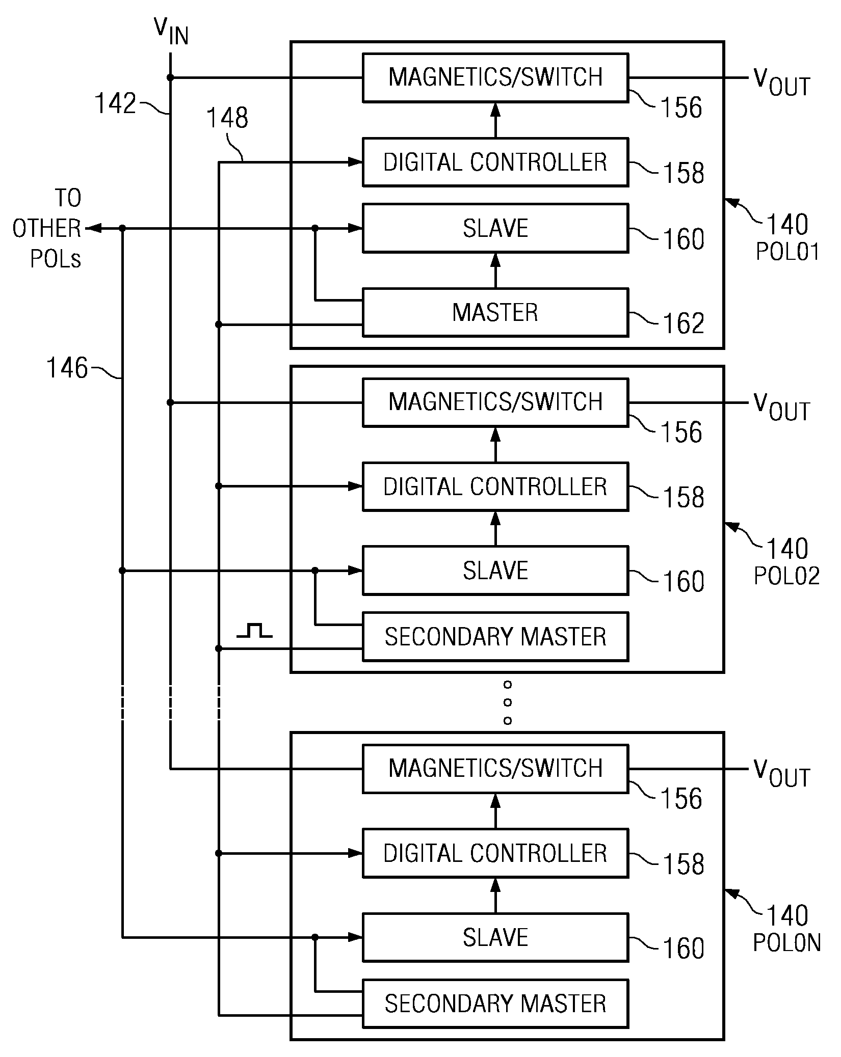
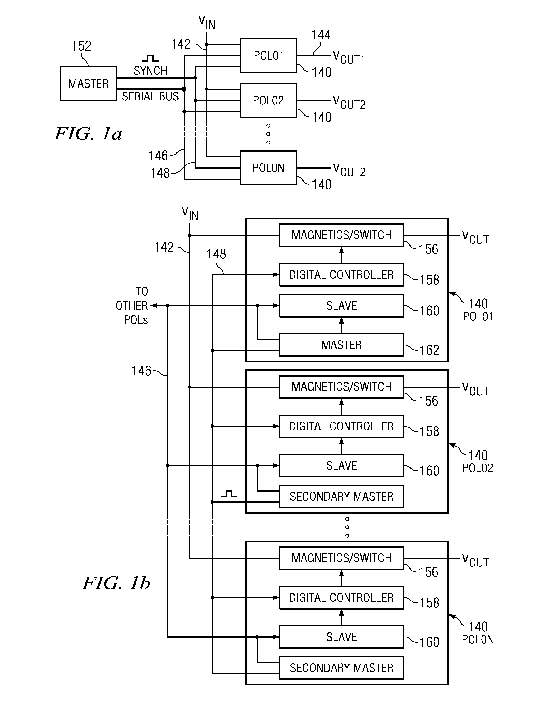
The present invention is a distributed power system that delivers DC power to multiple loads. It includes multiple power converter modules with associated DC to DC power conversion operations. Each module has a unique address and is connected to a data communication line for command data distribution. The processing section of each module can operate in both a slave mode to receive commands and a master mode to generate commands. The system also includes a processing section that can negotiate among the modules for assignment of a new master in case of failure. The technical effect of this invention is a more efficient and flexible distributed power system that allows for efficient power conversion and communication between modules.

Problems solved by technology

If this conversion is facilitated at a power supply and then connected to a remote microprocessor on a printed circuit board, the size of the conductor to handle the current and the associated I2R power loss would be large.
An additional problem may arise when the master controlling each of the POL DC to DC converters fails.

Method used


Image

  • Distributed power supply system having reassignable master
  • Distributed power supply system having reassignable master
  • Distributed power supply system having reassignable master

Examples


Embodiment Construction

[0083]Referring now to the drawings, wherein like reference numbers are used herein to designate like elements throughout the various views, embodiments of the present invention are illustrated and described, and other possible embodiments of the present invention are described. The figures are not necessarily drawn to scale, and in some instances the drawings have been exaggerated and / or simplified in places for illustrative purposes only. One of ordinary skill in the art will appreciate the many possible applications and variations of the present invention based on the following examples of possible embodiments of the present invention.

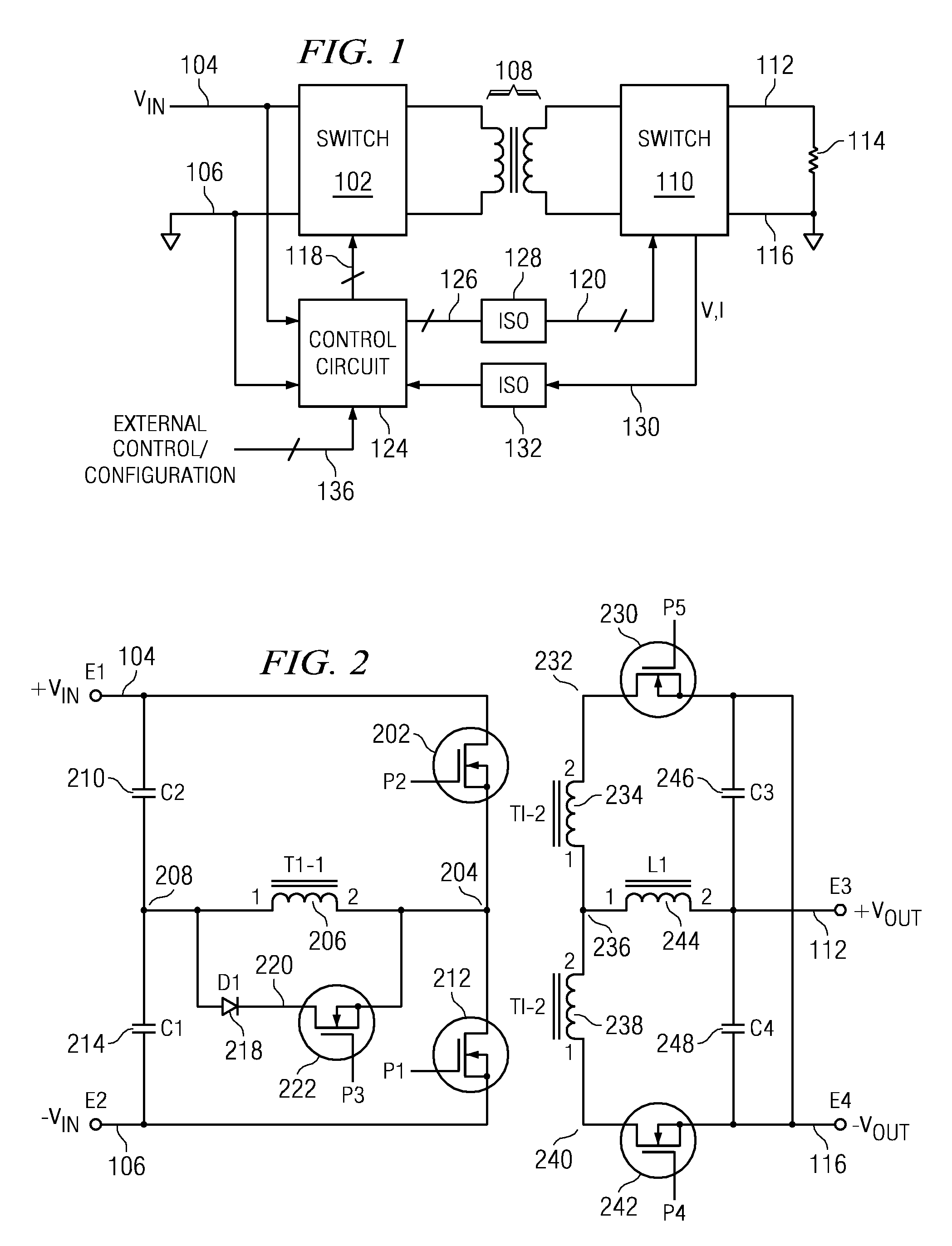
[0084]Referring now to FIG. 1, there is illustrated a top level schematic diagram for the switching power supply of the present embodiment, which in this Fig. is illustrated as a half bridge power supply. The main portion of the power supply comprises a primary switch group 102 that is operable to receive an input voltage on a node 104, this being a...


PUM


Abstract

A distributed power system delivers DC power to a plurality of loads. The distributed power system includes a plurality of power converter modules having an associated DC to DC power conversion operation. Each of the modules includes a power regulation section for receiving a distributed input power from a distributed power line to generate a DC output by controlling the operation of the switching pulse generator. A processing section within the module interfaces with a data communications line for interfacing with the commands. The processing section is capable of operating in both a slave mode to receive commands from said data communication bus and a master mode for generating the commands. In at least one of the modules operating in the master mode, the processing section generates the commands for transmission over the data communications line to an address of one of the other modules. Processing sections in the slave mode of operation are configurable to monitor the operation of said power regulation section. Processing sections in the slave mode of operation are further able to negotiate among active slaves for assignment of a selected module as a new master responsive to the failure of a previous master.

Description

CROSS-REFERENCE TO RELATED APPLICATIONS[0001]This application is a Continuation-in-part of U.S. Ser. No. 11 / 394,909 filed on Mar. 31, 2006, entitled “DISTRIBUTED POWER SUPPLY SYSTEM WITH SHARED MASTER FOR CONTROLLING REMOTE DIGITAL DC / DC CONVERTOR”, which is a Continuation-in-part application of U.S. Ser. No. 11 / 172,358, filed Jun. 30, 2005, entitled “FINITE STATE MACHINE DIGITAL PULSE WIDTH MODULATOR FOR A DIGITALLY CONTROLLED POWER SUPPLY,” which is a Continuation-in-part application of U.S. Ser. No. 11 / 096,597, filed on Mar. 31, 2005, entitled “DIGITAL PWM CONTROLLER” and it is related to U.S. patent application Ser. No. 11 / 096,598, filed Mar. 31, 2005, and entitled “PID BASED CONTROLLER FOR DC-DC CONVERTER WITH POST-PROCESSING FILTERS” and U.S. patent application Ser. No. 11 / 096,853, filed Mar. 31, 2005, and entitled “DIGITAL POWER SUPPLY CONTROLLER WITH VOLTAGE POSITIONING”, both of which are incorporated herein by reference in their entirety and claims priority in Provisional ...

Claims


Application Information

Patent Timeline
Patent Type & Authority Patents(United States)
IPC IPC(8): H02M3/335
CPCH02J1/08H02J13/0062H02M3/33515H02M3/33576H03K3/356121H03K3/35613H03K7/08H03M1/363H02J13/0003H02M2001/008H02J13/00016H02M1/008
Inventor FOSLER, ROSS M.ALFANO, DONALD E.
Owner SILICON LAB INC
Learn More