Vehicle safety device

a safety device and vehicle technology, applied in the direction of pedestrian/occupant safety arrangements, roofs, tractors, etc., can solve the problems of increased size of safety devices, increased cost or system complication, and limited installation sites, etc., and achieves a simple and low-cost mechanism

Inactive Publication Date: 2009-04-21
MAZDA MOTOR CORP
View PDF10 Cites 16 Cited by
  • Summary
  • Abstract
  • Description
  • Claims
  • Application Information

AI Technical Summary

Benefits of technology

[0010]Intended to provide a solution to the aforementioned problems of the prior art, the present invention has as an object the provision of a vehicle safety device which can provide an unobstructed forward view for a driver of a vehicle by lowering a hood which has once been lifted upward by means of a simple and low-cost mechanism.
[0012]In the vehicle safety device thus structured, the actuator applies an upward thrusting force to the hood from underside at a point close to the rear end of the hood of which forward end is joined to the vehicle body, causing the mechanical connector connecting the rear end of the hood to the vehicle body to extend, when an obstacle is detected. With this arrangement, the rear end of the hood is lifted in a swinging motion about a locking point where the forward end of the hood is locked to the vehicle body in the event of a collision with the obstacle. Therefore, the raised hood can receive the obstacle and effectively mitigate an impact acting on the obstacle in the collision.
[0013]According to the invention, the rod can be disengaged from the locking part by relatively turning the rod and the locking part about the longitudinal axis of the rod and, then, the rod can be retracted into the through hole in the locking part. Therefore, a user can contract the once extended mechanical connector and lower the hood quite easily to obtain an unobstructed forward view from a driver's seat.

Problems solved by technology

These prior art arrangements would inevitably entail higher cost or system complication.
Moreover, the prior art arrangements require a space for installing the motor 1 or the second actuator 9, so that the safety device increases in size and a site for installation thereof is limited.

Method used


Image

  • Vehicle safety device
  • Vehicle safety device
  • Vehicle safety device

Examples


first embodiment

[0038]A vehicle safety device 13 according to a first embodiment of the invention is now described with reference to FIGS. 1 to 11.

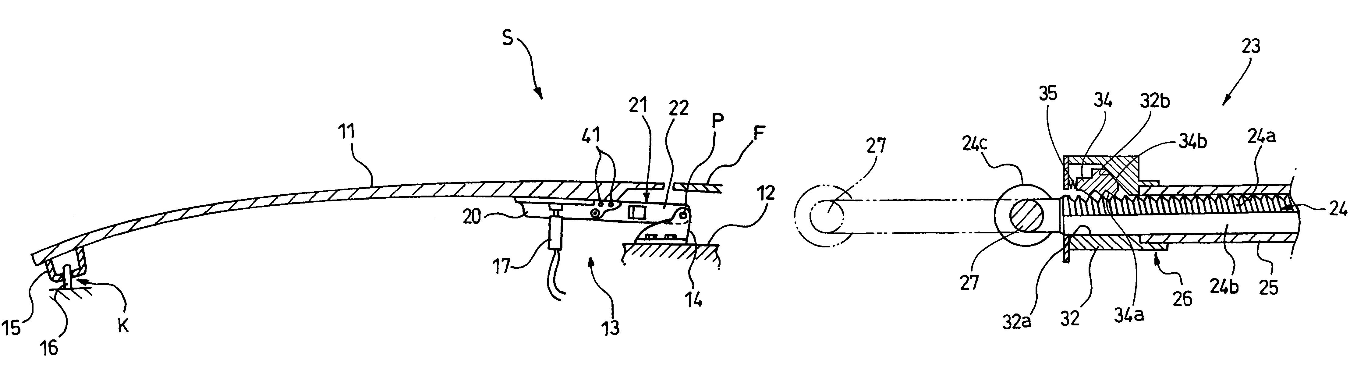
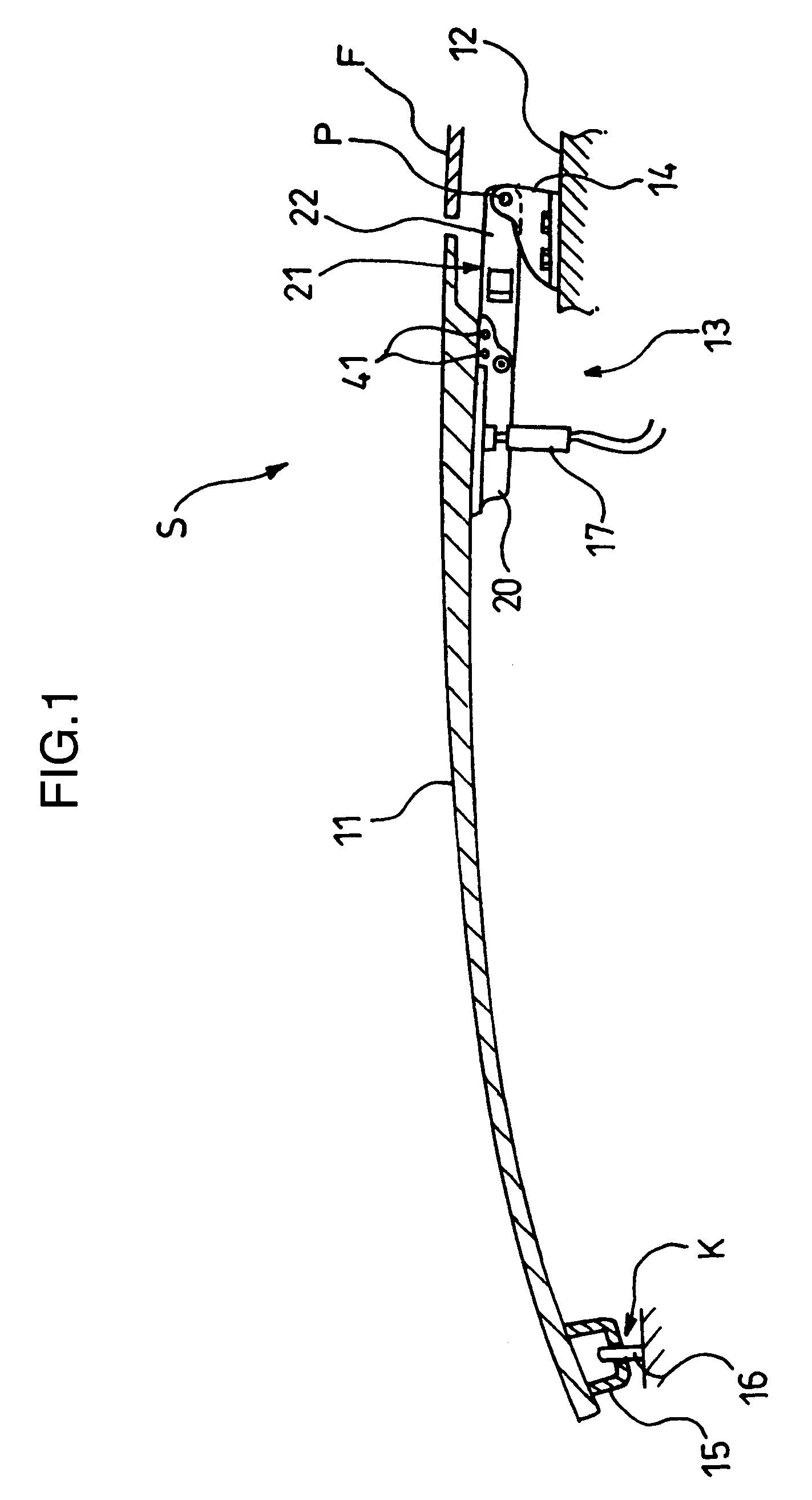
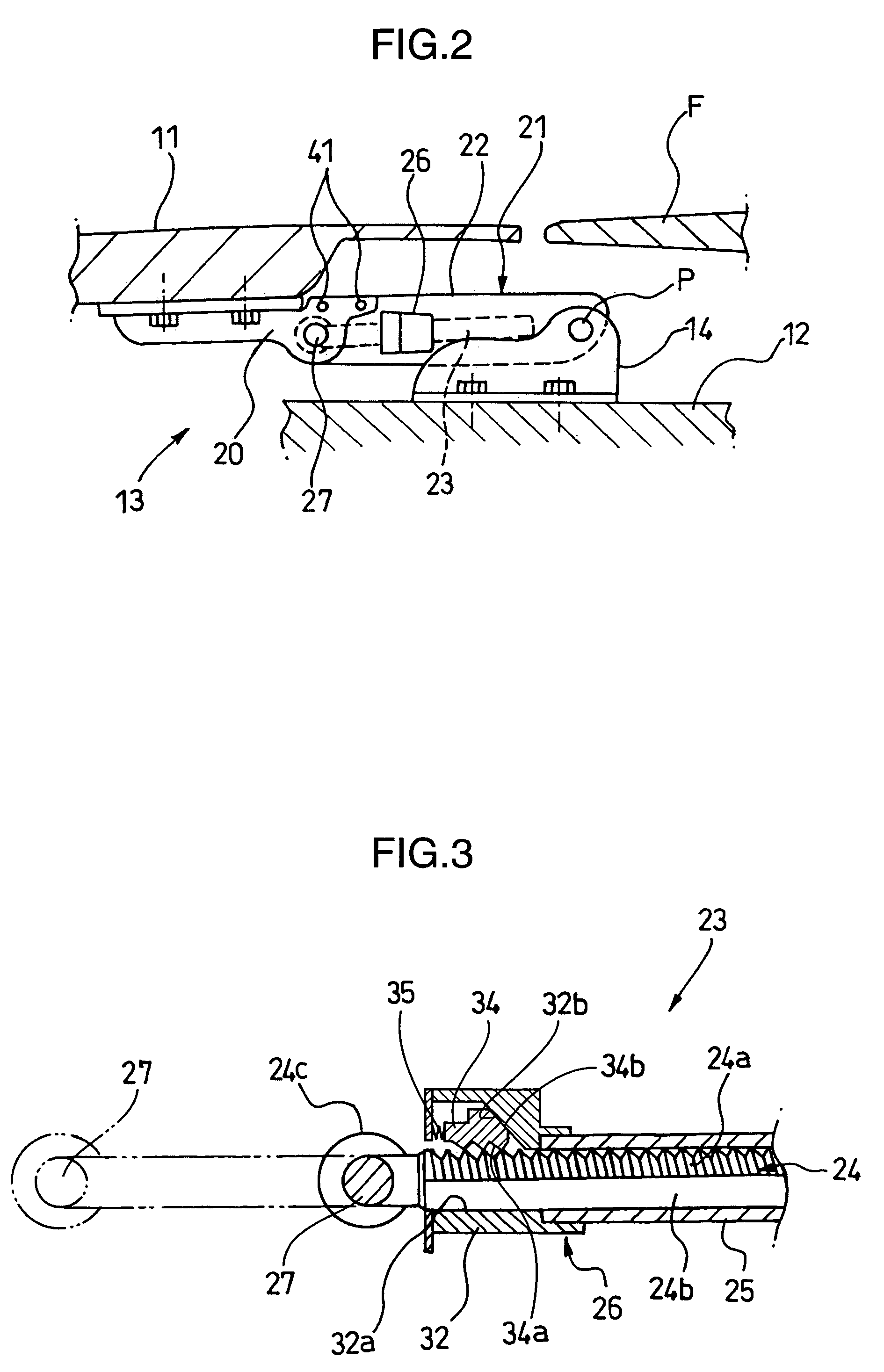
[0039]FIG. 1 is a side view of a hood 11 and associated components of a vehicle S provided with the vehicle safety device 13 of the first embodiment of the invention, FIG. 2 is a side view of the vehicle safety device 13, FIG. 3 is a sectional view of a lock mechanism constituting the vehicle safety device 13, FIGS. 4 and 5 are sectional views illustrating the working of the lock mechanism, FIG. 6 is a sectional view showing a structure for joining a stationary bracket 20 and a support bracket 14 of the vehicle safety device 13 to each other, and FIG. 7 is a sectional view illustrating how the hood 11 is opened and closed.

[0040]The hood 11 for covering the top of an engine room is provided at a frontal part of the vehicle S as shown in FIG. 1. The hood 11 is joined at a rear end portion thereof to a body 12 of the vehicle S. The vehicle safety device 13 ...

second embodiment

[0065]Now, a vehicle safety device 13 according to a second embodiment of the invention is described with reference to FIGS. 12 to 20, in which elements identical or similar to those of the first embodiment are designated by the same reference numerals and a description of such elements is not provided here.

[0066]FIG. 12 is a side view of a hood 11 and associated components of a vehicle S provided with the vehicle safety device 13 of the second embodiment of the invention, FIG. 13 is a side view of the vehicle safety device 13, FIG. 14 is a perspective view of the vehicle safety device 13, and FIG. 15 is a sectional view of the vehicle safety device 13 illustrating how the hood 11 is opened and closed.

[0067]Unlike the vehicle safety device 13 of the first embodiment, the vehicle safety device 13 of the second embodiment is provided with a movement restriction mechanism 51 between a stationary bracket 20 and a support bracket 14 as shown in FIGS. 12 to 14, the movement restriction me...


PUM


Abstract

A vehicle safety device (13) includes an actuator (17) which thrusts a hood (11) upward from underside at a point close to a rear end of the hood (11) to raise the same by a specific amount when an obstacle is detected, and a mechanical connector (21) which connects the rear end of the hood (11) to the vehicle body (12), the mechanical connector (21) being structured such that, when the actuator (17) raises the rear end of the hood (11), the mechanical connector (21) extends while swinging about a pivot (P) by which the mechanical connector (21) is joined to the vehicle body (12). The mechanical connector (21) includes a rod (24), and a locking part (26) having a through hole (32a) in which the rod (24) is inserted. The locking part (26) engages with the rod (24) in such a manner that the rod (24) can move in only one direction in which the rod (24) is extracted from the locking part (26), and the rod (24) is disengaged from the locking part (26) when turned about a longitudinal axis.

Description

BACKGROUND OF THE INVENTION[0001]1. Field of the Invention[0002]The present invention relates to a vehicle safety device provided on a hood which covers an engine room at a frontal part of a vehicle.[0003]2. Description of the Related Art[0004]Recent developments in automotive technology provide arrangements for lifting a hood of a vehicle covering an engine room in the event of a collision of a vehicle with an obstacle so that the raised hood would receive the obstacle and mitigate an impact acting on the obstacle in the collision (refer to Japanese Unexamined Patent Publication Nos. 2002-37125 and 2003-89362).[0005]An arrangement described in Japanese Unexamined Patent Publication No. 2003-89362 is such that a motor 1 turns when a control signal is fed from a control unit and, as a consequence, a movable plate 2 moves rearward and a link 3 connected to the movable plate 2 goes into an upright position in an interlocked fashion, whereby a rear part of a hood connected to the link 3...

Claims


Application Information

Patent Timeline
Patent Type & Authority Patents(United States)
IPC IPC(8): B60R21/34B60R21/38
CPCB60R21/38E05D11/00F15B15/19F15B15/261E05Y2900/536
Inventor YAMAGUCHI, HIROYOSHITAKAKURA, MINORUSHIMIZU, EIJIHIRATA, YORIMITSUWAKIIE, MITSURUFURUMOTO, ARIHIROEBISUGI, TAKASHI
Owner MAZDA MOTOR CORP
Why Eureka
Try Eureka