
Vehicle-operating apparatus

a technology of vehicle-operating apparatus and driving device, which is applied in the direction of mechanical control device, manual control with single controlling member, instruments, etc., to achieve the effect of reducing the time taken to operate the brake, and greatly enhancing the convenience of the driver

Inactive Publication Date: 2013-12-12
JUN GYO
View PDF12 Cites 6 Cited by
  • Summary
  • Abstract
  • Description
  • Claims
  • Application Information

AI Technical Summary

Benefits of technology

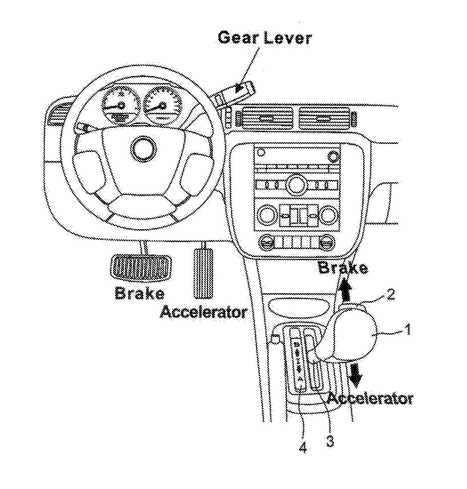
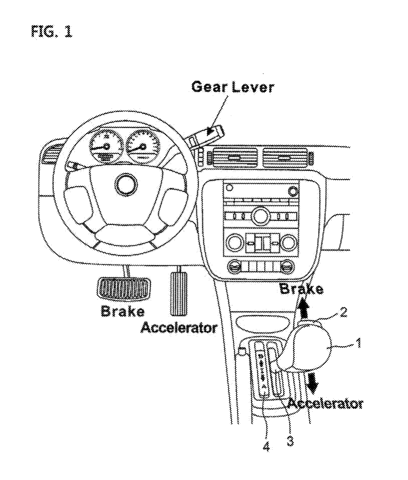
The vehicle driving apparatus described in this patent enhances driver convenience by allowing the driver to operate the brakes and accelerator with their hand instead of their foot. This is achieved by manipulating the brakes and accelerator with a single lever that the driver can operate while sitting in a chair-like posture. Compared to existing vehicles, the apparatus reduces the risk of accidents due to driver error. It also reduces the time taken to operate the brakes, improving reaction time in emergency situations. The brakes can be locked with a single button, eliminating the need for constant pressure, and the lever operates independently of the existing brakes or acceleration pedals, allowing the driver to choose their preferred mode of operation for increased convenience.

Problems solved by technology

However, the proposed patents have problems in that the manipulation handle is mounted to a neck portion of steering shaft so that a tilt function cannot be used and thus an angle of the steering wheel cannot be properly adjusted to be suitable for a user's body structure, and connecting rods which connect the manipulation handle and the accelerator and brake pedals may be caught up with the legs or arms, or obstruct the movement of the legs or arms when an ordinary person drives a vehicle so that the person feels uncomfortable and safe driving is hindered.
Among the apparatuses, the apparatus in which a single pedal combines the brake and the accelerator and is manipulated by a foot, is dangerous because a driver may accidentally incorrectly operate the pedal causing an accident to occur in an emergency situation, since a foot of a person is generally less accurate than the hand.

Method used


Image

  • Vehicle-operating apparatus
  • Vehicle-operating apparatus
  • Vehicle-operating apparatus

Examples


Embodiment Construction

Technical Problem

[0007]Therefore, the present invention has been made in view of the above-mentioned problems, and an aspect of the present invention is to provide a vehicle driving apparatus in which a brake and an accelerator are manipulated by using the hand instead of the foot so that convenience of a driver can be remarkably enhanced.

[0008]Another aspect of the present invention is to provide a vehicle driving apparatus which a driver can manipulate with his arm in a state where his arm feels most comfortable.

[0009]Another aspect of the present invention is to provide a vehicle driving apparatus in which, although a single lever is used, a brake and an accelerator are operated in opposite directions so that an accident is much less likely to occur due to driver error as compared with the existing vehicle.

[0010]Another aspect of the present invention is to provide a vehicle driving apparatus which can reduce the time taken to operate a brake as compared with the existing vehicle...


PUM


Abstract

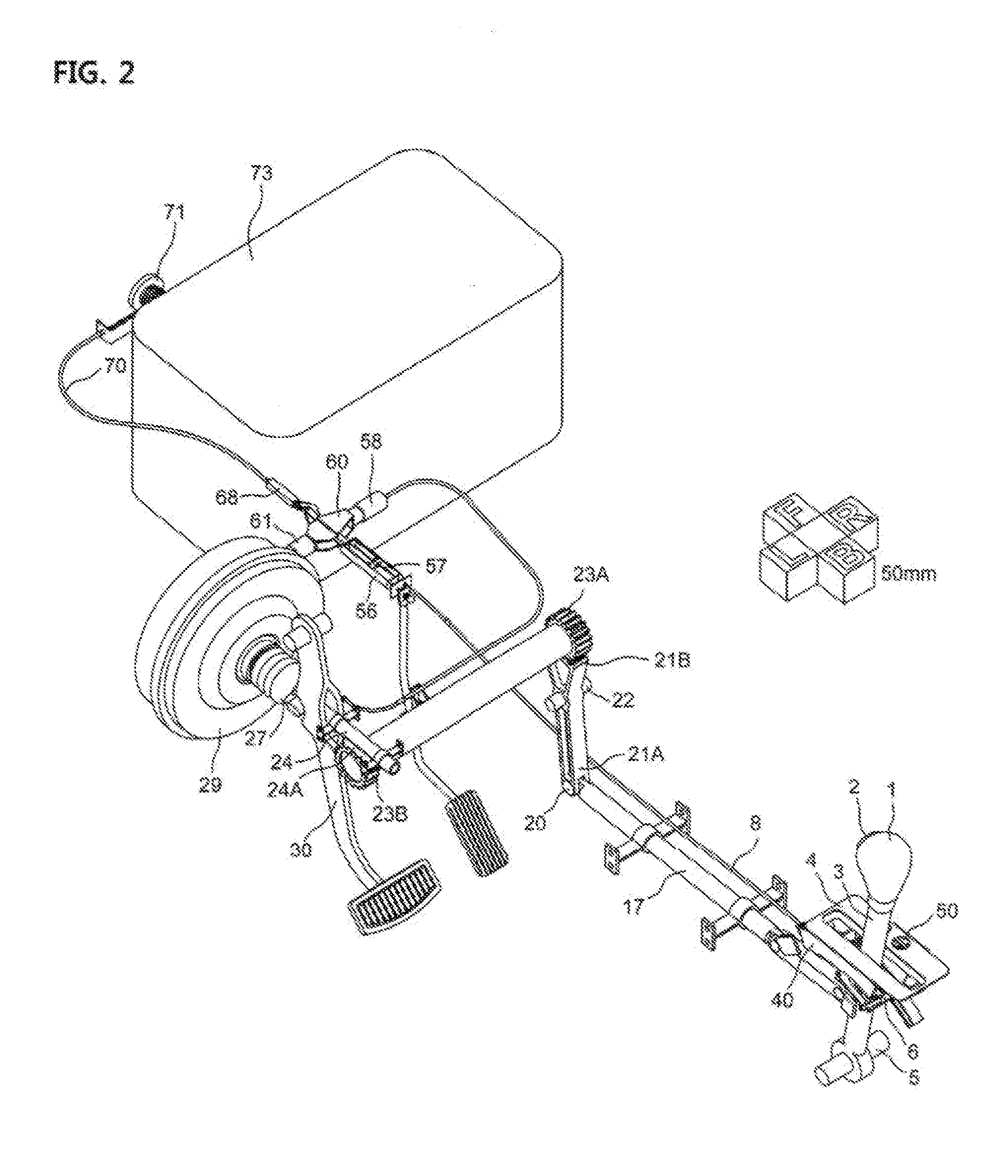
A vehicle driving apparatus where brake and acceleration functions are combined with a single stick includes: a lever moving to an acceleration position, an idle position, or a brake position as rotating forward and rearward about a shaft fixed to a vehicle body at a predetermined angle; a hand acceleration means opening an engine throttle to cause a vehicle to be accelerated; a hand brake means pushing a booster rod of a brake booster so that a brake operates to cause the vehicle to be stopped; a guide means installed on the left and right sides of the lever to prevent the lever from being shaken leftward and rightward; a hand brake locking means allowing the hand brake to be continuously applied; and a cruise control means allowing the lever to stay in the acceleration position even if the driver takes his hand off the lever.

Description

TECHNICAL FIELD[0001]The present invention relates to a vehicle driving apparatus in which brake and acceleration functions are coupled to a single stick, and more particularly, to a vehicle driving apparatus in which a single lever which a driver can manipulate simultaneously performs brake and accelerator functions, so that convenience of the driver can be remarkably enhanced.BACKGROUND ART[0002]A driving assist apparatus which enables an accelerator pedal and a brake pedal to be operated by a hand has been proposed by KR pat. Nos. 1991-0004895 and 1991-0004896, in which a manipulation handle is installed in a direction approximately perpendicular to a shaft of a steering wheel, and the manipulation handle is rotated about any one point, so that control of acceleration, speed-up, and speed-down can be performed according to a rotation direction and a rotation angle of the manipulation handle.[0003]However, the proposed patents have problems in that the manipulation handle is mount...

Claims


Application Information

Patent Timeline
Patent Type & Authority Applications(United States)
IPC IPC(8): G05G11/00G05G9/02
CPCB60K41/20G05G9/02B60K20/06B60K26/02B60K2026/029B60W30/18181B60W2710/06B60W2710/18Y10T74/2022Y10T74/20226B60K20/00B60K26/00B60W30/00
Inventor JUN, GYO
Owner JUN GYO
Learn More