Luminaire comprising LEDs

a technology of leds and luminaires, applied in the field of luminaires, can solve the problems of limiting the freedom of design of luminaires, fixed placement, and complex light guides

Active Publication Date: 2009-04-21
SIGNIFY HLDG BV
View PDF12 Cites 83 Cited by
  • Summary
  • Abstract
  • Description
  • Claims
  • Application Information

AI Technical Summary

Benefits of technology

[0007]In accordance with an aspect of the present invention, there is provided a luminaire comprising a housing having an opening at a light output side; a reflector mounted within the housing and facing the light output side; and a louver arranged at the opening. The louver is spaced from the reflector, and has a geometric shape, which opens towards the reflector. Further, the luminaire has a plurality of LEDs, which are arranged in the louver and which emit light onto the reflector. The light is reflected at the reflector and constitutes a light output of the luminaire. The louver prevents direct light emission from the LEDs towards the opening of the housing, and prevents glare.
[0008]By using the louver as a support for the LEDs it is possible to freely choose the placement of the LEDs, and thereby the shape of the reflector as well, for obtaining different light distribution as desired.
[0010]In an embodiment of the luminaire according to this invention, as defined in claim 4 the LEDs are arranged in a V-shaped louver, facilitating the mounting of the LEDs and providing a good screening effect.

Problems solved by technology

The prior art luminaire has several disadvantages, among others the fixed placement of the LEDs, restricting the freedom in designing the luminaire, and the complex light guide.

Method used


Image

  • Luminaire comprising LEDs
  • Luminaire comprising LEDs
  • Luminaire comprising LEDs

Examples


first embodiment

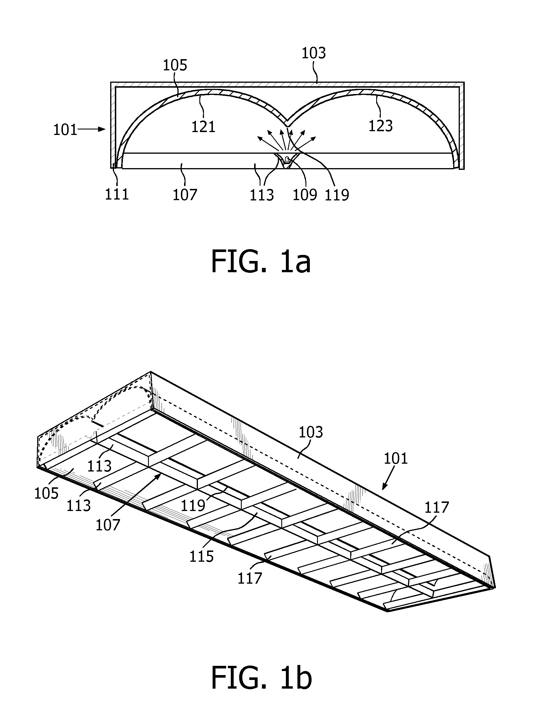
[0020]a luminaire 101 according to the present invention comprises a housing 103, a reflector 105, a louver 107, and a plurality of Light Emitting Diodes (LEDs) 109. The housing 103 is box shaped and has a bottom opening 111, the bottom constituting a light output side of the housing 103. The reflector 105 is mounted within the housing 103, the reflecting surface facing downwards towards the opening 111. The louver 107 is engaged with side edge portions of the housing 103 at the opening 111. The louver 107 has several elongated louver portions 113 forming a grid. The grid consists of a longitudinal center louver portion 115, extending along the length of the housing 103 at the center of the opening 111, and a plurality of branch louver portions 117 extending perpendicular to the center louver portion 115, and extending between the long sides of the housing 103. The louver portions 113 are substantially V-shaped in cross-section, and more particularly the two walls of each louver por...

second embodiment

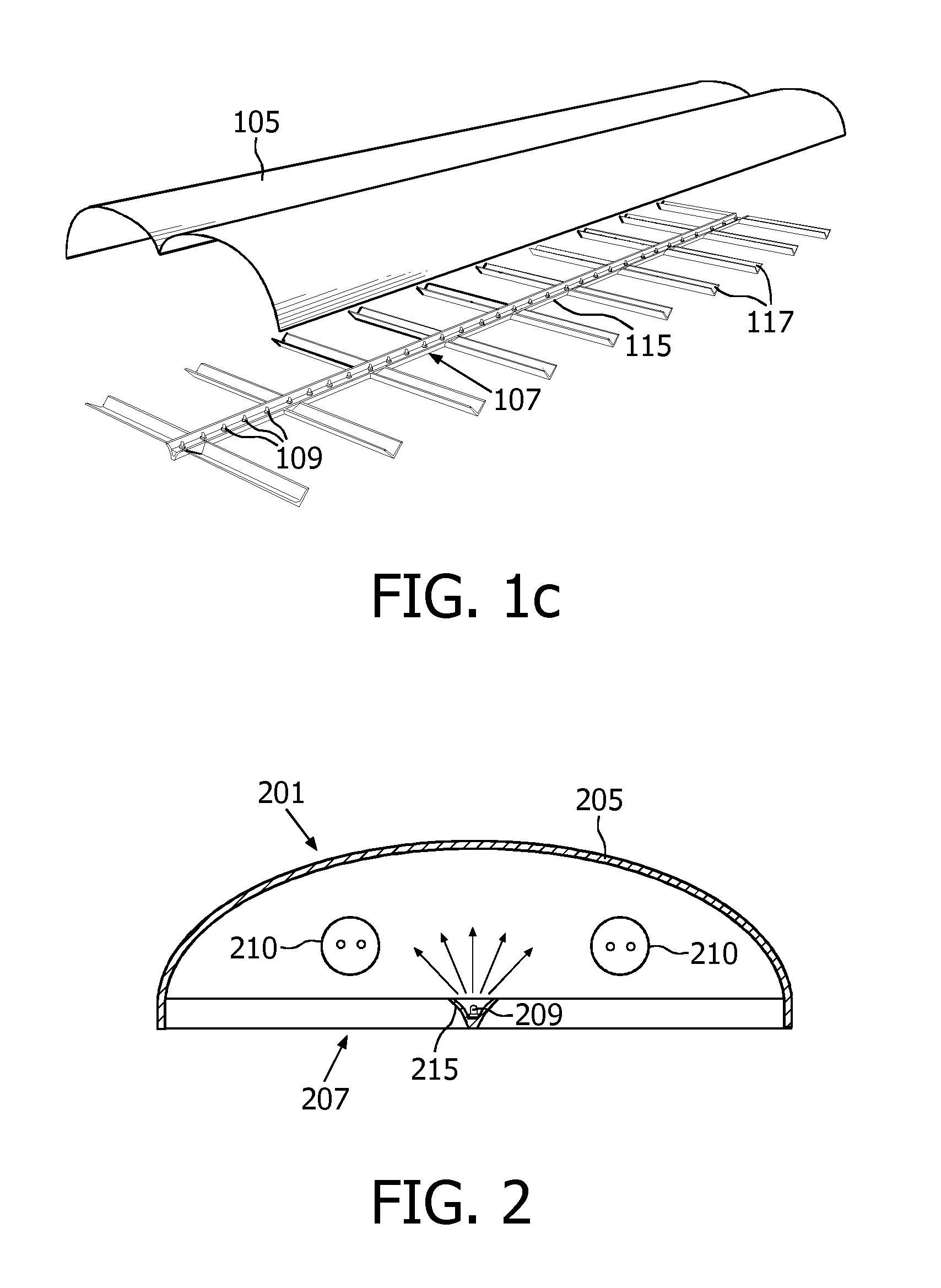
[0024]In this second embodiment the LEDs 209 are combined with the lamps 210 in order to enable tuning of the light output. For example, the LEDs 209 can be used for adding colored light to the light of the second light source 210, which commonly is emitting white light. In this way the white light can be made more cool or warm or pastel colors can be realized. If the LEDs 209 are RGB LEDs arbitrary colors can be added. By making both light sources, i.e. the LEDs 209 and the lamps 210, individually dimmable a color balancing is performable. Then, for example, the saturated light emitted from the LEDs 209 can be made more pastel by adding white light emitted from the second light source 210.

[0025]Alternatively, the LEDs 209 can provide a decorative color effect in the luminaire, when the second light source 210 is dimmed or switched off.

[0026]Referring now to FIGS. 3a and 3b, a third embodiment of a luminaire according to this invention comprises a dome shaped reflector 305, a louver...


PUM


Abstract

This invention relates to a luminaire (106), which has a housing (103) with an opening (111) at a light output side, a reflector (105) mounted in the housing, and facing the light output side, a louver (107) mounted at the opening of the housing, and LEDs (109) mounted in the louver, such that the emitted LED light exits the luminaire only after reflection against the reflector, thereby providing indirect light output.

Description

FIELD OF THE INVENTION[0001]The present invention relates to a luminaire comprising a housing having an opening at a light output side, a reflector mounted within the housing and facing the light output side and a plurality of LEDs as light sources using the reflector for providing indirect light output.BACKGROUND OF THE INVENTION[0002]A prior art luminaire of the above-mentioned type is disclosed in the German Patent Application publication No. DE 103 14 257 A1. The German prior art Luminaire has a reflector having a center longitudinal opening wherein a longitudinally co-extending light guide is arranged. Behind the light guide an array, and more particularly a row, of LEDs is arranged along the length of the light guide. The light emitted from the LEDs pass through the light guide. A part of the LED light is deflected by the light guide towards the surface of the reflector, and is reflected by the reflector towards a light output side of the luminaire, and the rest of the LED lig...

Claims


Application Information

Patent Timeline
Patent Type & Authority Patents(United States)
IPC IPC(8): F21V7/06
CPCF21V7/0008F21V11/06F21S9/022F21V19/001F21V23/04F21Y2101/02F21Y2103/00F21Y2113/00F21Y2113/02F21V11/02F21V7/005F21V7/06F21Y2113/20F21Y2115/10F21V7/00
Inventor VAN DER POEL, LUCAS LEO DESIREE
Owner SIGNIFY HLDG BV
Why Eureka
Try Eureka