Non-cylindrical filter elements, and methods

a filter element and non-cylindrical technology, applied in the field of fluid filters, to achieve the effect of increasing the outlet area, reducing the pressure drop, and reducing the outlet velocity

Active Publication Date: 2009-04-21
DONALDSON CO INC
View PDF13 Cites 91 Cited by
  • Summary
  • Abstract
  • Description
  • Claims
  • Application Information

AI Technical Summary

Benefits of technology

[0007]Various problems are solved by the design of the present disclosure. The filter element of the present disclosure, by having a non-circular outlet aperture, increases the outlet area to thus decrease outlet velocity and decrease pressure drop. The non-circular cross-section limits the possible orientations for adjoining ductwork, which is desired for some installations; a circular outlet has infinite orientations, which may be a non-preferred configuration for some installations.

Problems solved by technology

The non-circular cross-section limits the possible orientations for adjoining ductwork, which is desired for some installations; a circular outlet has infinite orientations, which may be a non-preferred configuration for some installations.

Method used


Image

  • Non-cylindrical filter elements, and methods
  • Non-cylindrical filter elements, and methods
  • Non-cylindrical filter elements, and methods

Examples


Embodiment Construction

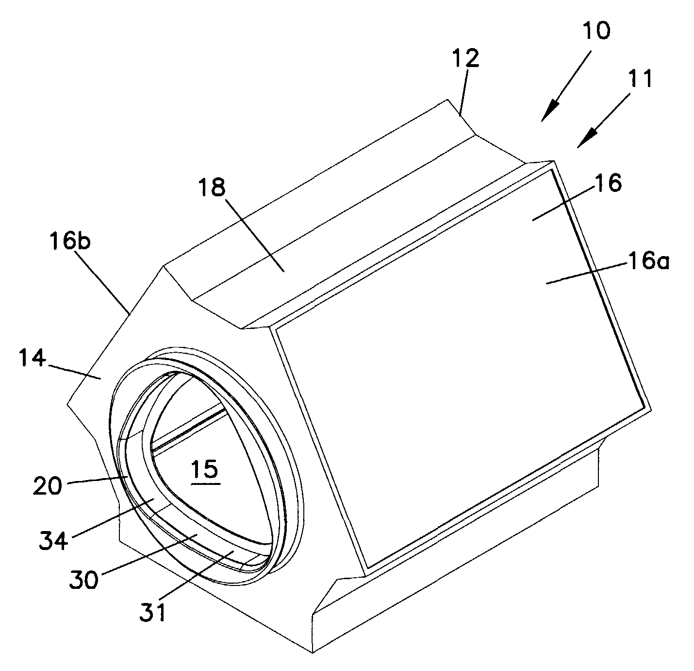
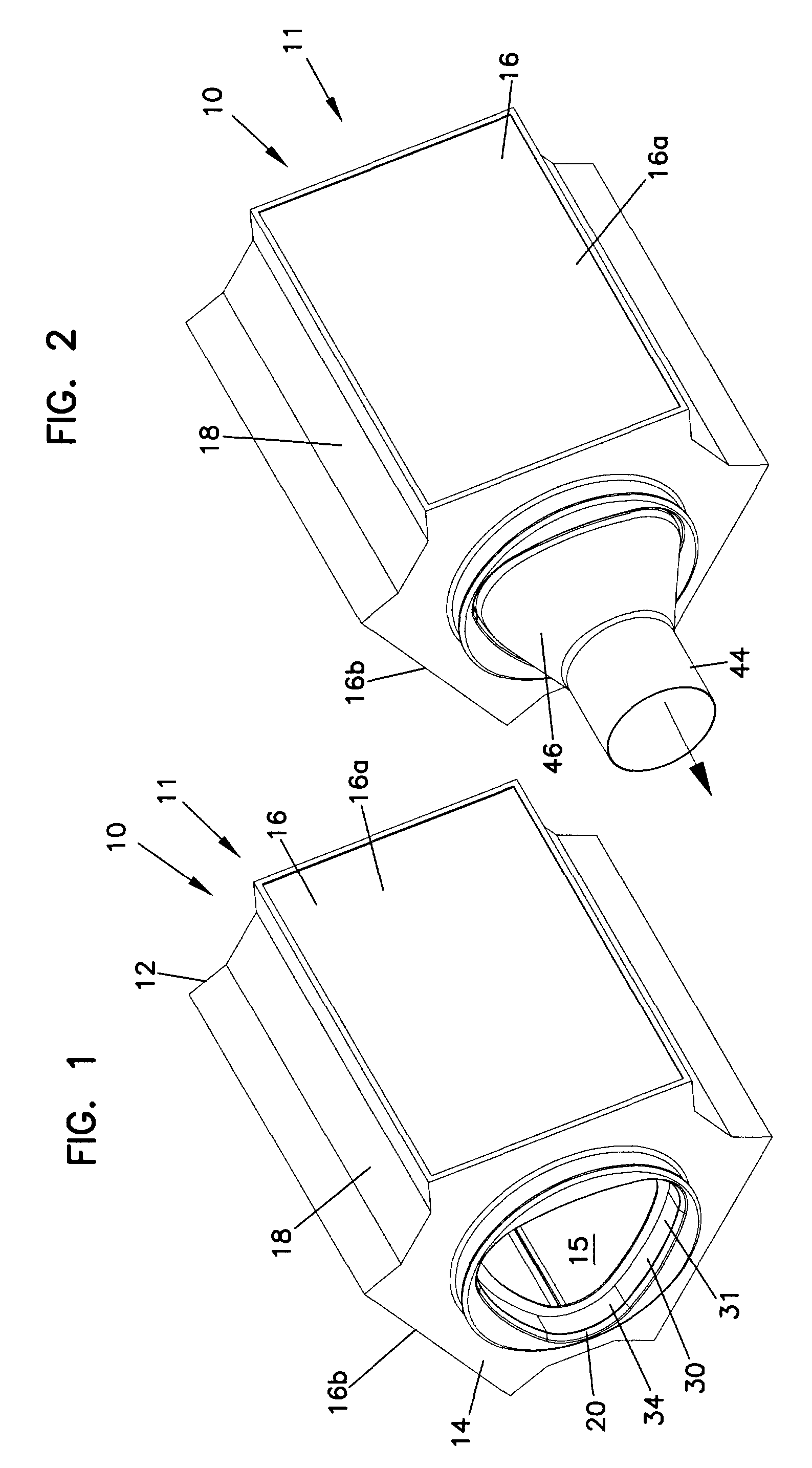
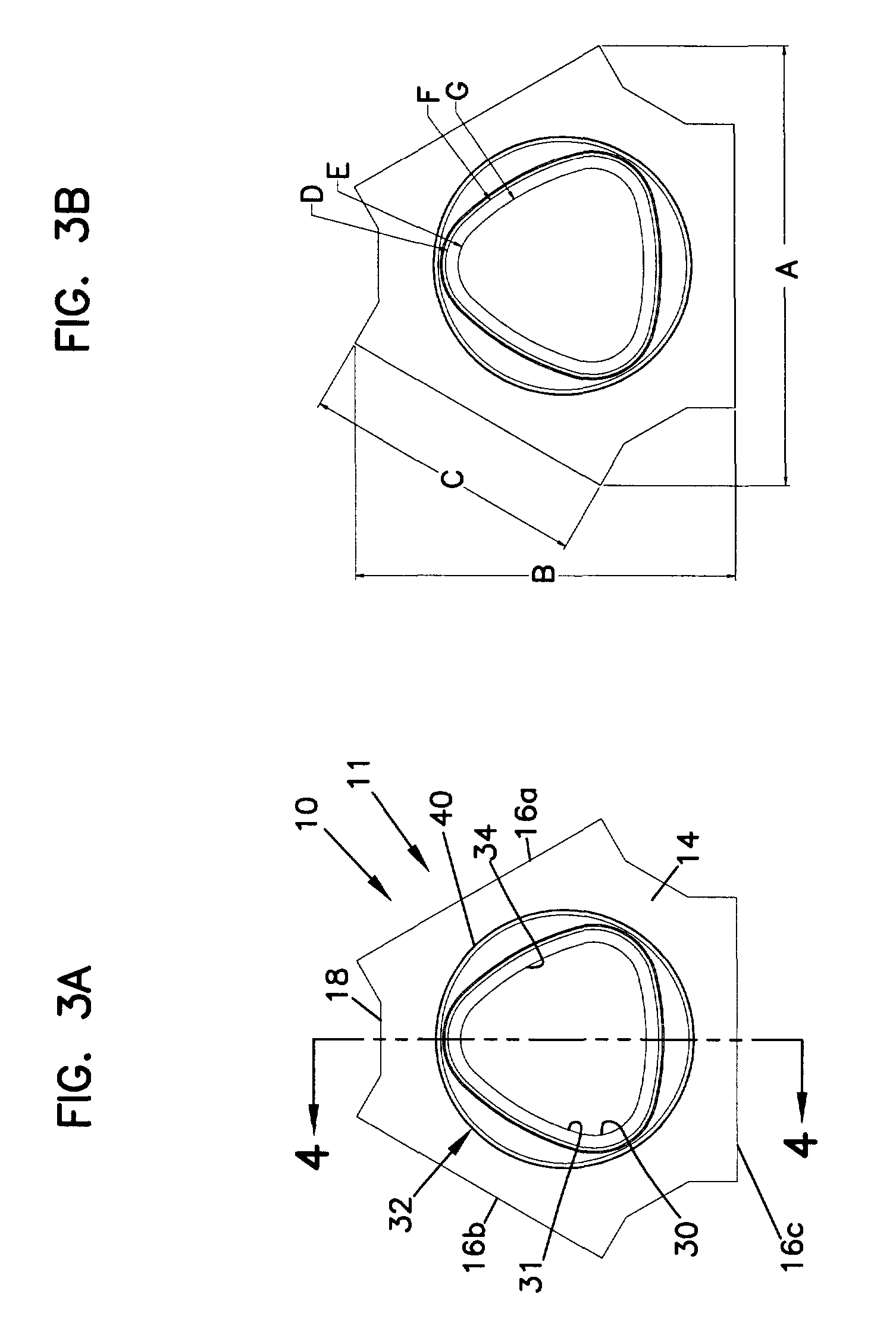
[0019]Referring now to the Figures, a filter element according to the present invention is shown at 10 in FIGS. 1 through 4B. Filter element 10 is a fluid filter; that is, filter element 10 filters out or removes contaminants from a fluid stream. In many embodiments, filter element 10 is a gas filter, configured for removal of contaminants from a gas stream. In most embodiments, the gas being filtered is air. Filter element 10 is particularly suitable for use in an aircraft or other lightweight vehicle, for filtering cabin air. In a passenger aircraft, filter element 10 would generally be located in a cargo hold, below the passenger cabin.

[0020]In use, filter element 10, in many embodiments, is removably positioned in a housing, duct, or other structure. The housing, duct or other structure may or may not complete enclose or envelope filter element 10.

[0021]Filter element 10 has a first end 12 and an opposite second end 14. Filter element includes filtration panels 16 and support st...


PUM

PropertyMeasurementUnit
surface angleaaaaaaaaaa

Abstract

A filter element that has at least two, planar, non-curved filtration panels. In a preferred embodiment, the filter element has three panels, providing a generally triangular filter element. The outlet aperture, from the filter element, generally follows the configuration of the filter. That is, a filter element having three filtration panels will have a generally three-sided outlet aperture. The outlet aperture preferably is not a true polygon, but rather, includes rounded or curved sides and / or corners. The filter element includes an outlet sealing configuration that may provide both axial and radial sealing to outlet ductwork.

Description

[0001]Priority under 35 U.S.C. § 119(e) is claimed to provisional application Ser. No. 60 / 650,019 filed Feb. 4, 2005 and to provisional application Ser. No. 60 / 733,978 filed Nov. 3, 2005. The complete disclosures of applications 60 / 650,019 and 60 / 733,978 are incorporated by reference herein.FIELD[0002]The present invention relates to a fluid filter for removing contaminants from a gaseous stream, such as an air stream.BACKGROUND[0003]Filter elements are used in many industries to remove airborne contaminants to protect people, the environment, and often, a critical manufacturing process or the products that are manufactured by the process.[0004]There is always a need to design different filter elements.SUMMARY OF THE INVENTION[0005]Non-cylindrical filter elements are provided. Preferably, the filter elements have at least two flat or planar filtration panels. Fluid, such as air, to be filtered enters the filter element through the panels, preferably through each of the panels. An ou...

Claims


Application Information

Patent Timeline
Patent Type & Authority Patents(United States)
IPC IPC(8): B01D46/52B01D29/07B01D29/11
CPCB01D46/002B01D46/0036B01D46/10B01D46/521B01D39/1607B01D46/0005B01D2271/02B01D2275/206B01D2275/10B01D46/58B01D2271/027
Inventor MILLS, JARREN B.ADAMEK, DANIEL E.DEJONG, RICHARD
Owner DONALDSON CO INC
Why Eureka
Try Eureka