Coordinate-based display object movement restriction method

a technology of display object and movement restriction, which is applied in the direction of instruments, computing, electric digital data processing, etc., can solve the problems of taking a long time to determine a direction, and the operation of continuously advancing directly in the direction of the x-axis or the y-axis on the display screen is difficul

Inactive Publication Date: 2009-04-21
SHARP KK
View PDF13 Cites 29 Cited by
  • Summary
  • Abstract
  • Description
  • Claims
  • Application Information

AI Technical Summary

Problems solved by technology

However, in the pointing device using the gyrosensor according to these prior art, as the inclination of the body of the pointing device using the gyrosensor is detected as linear movement in a direction according to the inclination, the pointing device has a defect that an operation for continuously advancing directly in a direction of the x-axis or in a direction of the y-axis on a display screen is difficult, a component in the other direction is mixed without fail and movement to be direct curves.
The pointing device also has a problem that it takes much time to determine a direction because the direction is not determined until a predetermined value is acquired by using a method of determining either of the x-axis or the y-axis on which the whole movement amount reaches the predetermined value earlier as a motional direction, resetting when the direction is determined and repeating it.

Method used


Image

  • Coordinate-based display object movement restriction method
  • Coordinate-based display object movement restriction method
  • Coordinate-based display object movement restriction method

Examples


Embodiment Construction

[0010]Referring to the drawings, an embodiment of the invention will be described below.

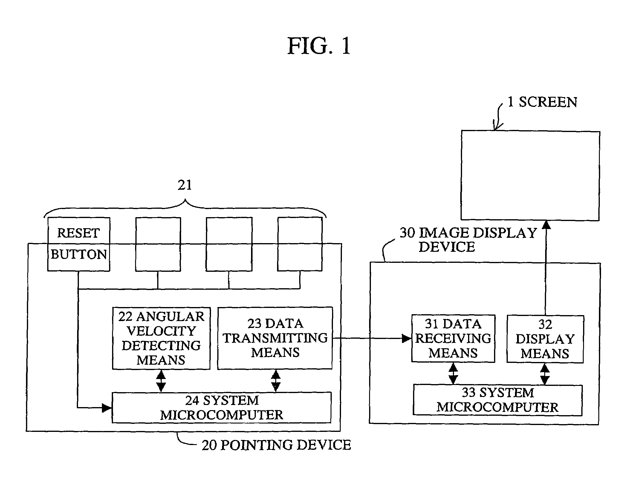
[0011]FIG. 1 is a block diagram showing the configuration of a display device for presentation according to the invention. As shown in FIG. 1, a reference number 1 denotes a screen. A reference number 20 denotes a pointing device and the pointing device is formed by a group of buttons 21 such as reset buttons, angular velocity detecting means 22, data transmitting means 23 and a pointing device system microcomputer 24. A reference number 30 denotes an image display device and the image display device is formed by data receiving means 31, display means 32 and an image display device system microcomputer 33.

[0012]In the angular velocity detecting means 22, each velocity sensor such as a gyrosensor is built, converts three-dimensional information to two-dimensional information in a horizontal direction and in a vertical direction, reads (samples) relative positional information before and after move...


PUM


Abstract

A component in a horizontal direction (the x-axis component) of a movement amount first acquired after a pointing device is reset and a component in a vertical direction (the y-axis component) are compared, a movement input is regarded as provided only in the horizontal direction in case the absolute value of the x-axis component is larger than the absolute value of the y-axis component, a movement input is regarded as provided only in the vertical direction in case the absolute value of the y-axis component is larger than the absolute value of the x-axis component, a movement input is regarded as provided in the same direction unless the ratio of components of movement inputs is greatly changed subsequently, and continuous movement inputs in the same direction are facilitated.

Description

TECHNICAL FIELD[0001]The present invention relates to a pointing device using a gyrosensor and a display device for presentation using a projection type image display device such as a liquid crystal projector.BACKGROUND ART[0002]Recently, cases that an image by a computer and a dynamic image are displayed using a projection type image display device such as a liquid crystal projector and effective presentation is made using a pointing device increase, and a device that utilizes a gyrosensor for the pointing device is proposed. The pointing device utilizing the gyrosensor moves the body to a specific direction, samples the information of relative positions before and after the movement every fixed time, and transmits the relative positional information to the display device. The display device moves a selected position of a menu item included in a main menu on the screen based upon the received relative positional information, moves and the cursor and a point, pans and moves a pictur...

Claims


Application Information

Patent Timeline
Patent Type & Authority Patents(United States)
IPC IPC(8): G06F3/033G06F3/041G06F3/0346
CPCG06F3/038G06F3/0346
Inventor ARAKAWA, KAZUYAFURUHASHI, TOSHINORIKOJIMA, SHIGERU
Owner SHARP KK
Why Eureka
Try Eureka