Multi-coil coupling system for hearing aid applications
What is AI technical title?
AI technical title is built by Patsnap AI team. It summarizes the technical point description of the patent document.
a coupling system and hearing aid technology, applied in the direction of deaf-aid sets, electrical equipment, electronic input selection/mixing, etc., can solve the problems of high background noise, hearing impaired individuals often have great difficulty carrying on normal conversations in noisy environments, and may require a hearing solution
Inactive Publication Date: 2009-04-21
III HLDG 7
View PDF22 Cites 98 Cited by
Summary
Abstract
Description
Claims
Application Information
AI Technical Summary
This helps you quickly interpret patents by identifying the three key elements:
Problems solved by technology
Method used
Benefits of technology
Problems solved by technology
In many situations, however, hearing impaired individuals may require a hearing solution beyond that which can be provided by such a hearing aid using it's internal microphone alone.
For example, hearing impaired individuals often have great difficulty carrying on normal conversations in noisy environments, such as parties, meetings, sporting events or the like, involving a high level of background noise.
In addition, hearing impaired individuals also often have difficulty listening to audio sources located at a distance from the individual, or to several audio sources located at various distances from the individual and at various positions relative to the individual.
The characteristics and location of a hearing aid internal microphone often results in excessive pickup of ambient acoustical noise.
A common problem with prior art tele-couplers of the neck loop and silhouette styles has been the difficulty of bathing the telecoil in a magnetic field that is both of sufficient strength and sufficient uniformity in relation to typical relative tele-coupler / telecoil positionings so as ensure a predictable, consistent audio coupling at a volume level that is adequate for comfortable use and that can consistently overcome environmental magnetic noise interference.
Additionally, silhouette-style tele-couplers, which are generally designed with BTE aids in mind, have not successfully achieved sufficient field strength at the greater distance needed to reach ITE telecoils, or provided the appropriate field orientation for optimum coupling.
Further, the net frequency response obtained with prior art tele-coupler / telecoil systems has been uncontrolled, unpredictable, and generally not uniform.
The combination of the non-uniform frequency characteristics of the field produced by the typical transmitting inductor and the non-uniform frequency response of the typical receiving telecoil results in unsatisfactory overall frequency response for the user.
Method used
Image
Click on the blue label to locate the original text in one second.
Reading with bidirectional positioning of images and text.
Examples
Embodiment Construction
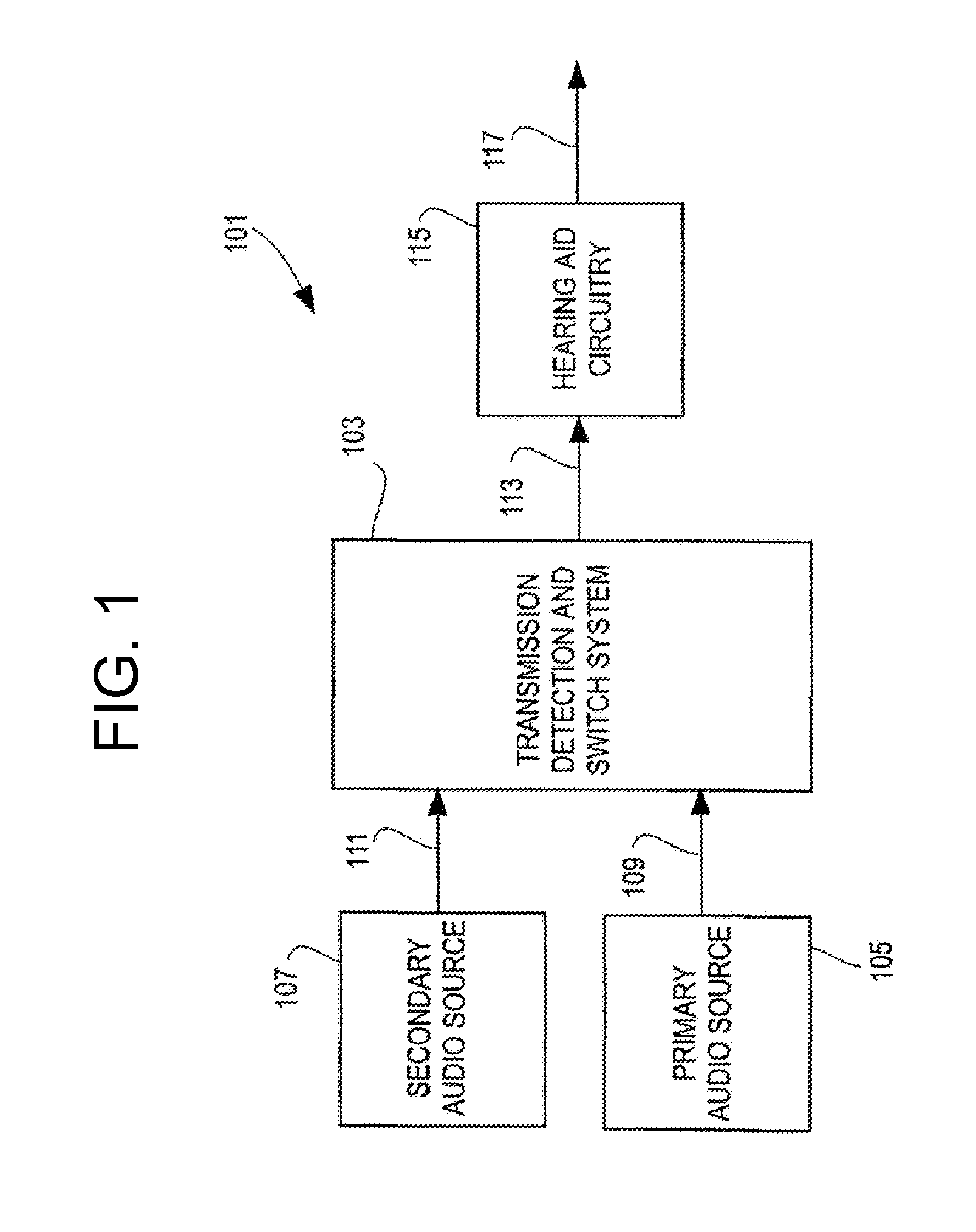
[0057]FIG. 1 is a block diagram of an overall hearing improvement system 101 of the present invention. A transmission detection and switch system 103 receives signals from both a primary audio source 105 and a secondary audio source 107. The primary audio source 105 may be, for example, a directional or omnidirectional microphone located in a hearing aid. The secondary audio source 107 may be, for example, a directional microphone / transmitter mounted on eyeglasses (or otherwise supported by a hearing aid user), a television or stereo transmitter, a telephone or a microphone / transmitter combination under the control of a talker. In one embodiment, the secondary audio source 107 utilizes a wireless transmission scheme for transmission of signals to the transmission detection and switch system 103. In another embodiment, the secondary audio source 107 is wired to the transmission detection and switch system 103.
[0058]In operation, the transmission detection and switch system 103, which...
PUM
Abstract
A hearing improvement device using a multi-coil coupling system and methods for operating such a device are disclosed. An embodiment of the present invention may use an array microphone to provide highly directional reception. The received audio signal may be filtered, amplified, and converted into a magnetic field for coupling to the telecoil in a conventional hearing aid. Multiple transmit inductors may be used to effectively couple to both in-the-ear and behind-the-ear type hearing aids, and an additional embodiment is disclosed which may be used with an earphone, for users not requiring a hearing aid.
Description
CROSS-REFERENCE TO RELATED APPLICATIONS / INCORPORATION BY REFERENCE[0001]This application is a continuation of prior U.S. patent application Ser. No. 10 / 356,290 entitled “Multi-Coil Coupling System For Hearing Aid Applications” filed Jan. 31, 2003 now U.S. Pat. No. 7,099,486, which is itself a continuation in part of U.S. patent application Ser. No. 09 / 752,806, entitled “Transmission Detection and Switch System for Hearing Improvement Applications”, filed on Dec. 28, 2000 now U.S. Pat. No. 6,694,034, that in turn makes reference to, claims priority to, and claims the benefit of U.S. Provisional Patent Application Ser. No. 60 / 174,958 filed Jan. 7, 2000, Ser. No. 60 / 225,840 filed Aug. 16, 2000, and Ser. No. 60 / 123,004 filed Mar. 5, 1999, the complete subject matter of each of which is hereby incorporated herein by reference, in its entirety.[0002]This application also makes reference to U.S. Pat. No. 6,009,311, issued Dec. 28, 1999, the complete subject matter of which is hereby incorp...
Claims
Application Information
Patent Timeline
Application Date:The date an application was filed.
Publication Date:The date a patent or application was officially published.
First Publication Date:The earliest publication date of a patent with the same application number.
Issue Date:Publication date of the patent grant document.
PCT Entry Date:The Entry date of PCT National Phase.
Estimated Expiry Date:The statutory expiry date of a patent right according to the Patent Law, and it is the longest term of protection that the patent right can achieve without the termination of the patent right due to other reasons(Term extension factor has been taken into account ).
Invalid Date:Actual expiry date is based on effective date or publication date of legal transaction data of invalid patent.

