Optical coupler for in vivo examination of biological tissue

an optical coupler and biological tissue technology, applied in the direction of instruments, catheters, fluorescence/phosphorescence, etc., can solve the problems of inability to use pulse oximeters, inability to detect errors, etc., to achieve excellent coupling of ligh

Inactive Publication Date: 2009-01-29
CHANCE BRITTON
View PDF9 Cites 75 Cited by
  • Summary
  • Abstract
  • Description
  • Claims
  • Application Information

AI Technical Summary

Benefits of technology

[0041]In general, the optical coupling system provides an excellent coupling of light to the examined tissue. The coupling system may also substantially prevent escape of photons from the tissue surface and achieve semi-infinite boundary conditions for the introduced radiation. A larger volume of optical medium is usually used for a small tissue size. The optical coupling system also achieves precisely a selected geometry of the input (excitation) ports and the detection ports regardless of the tissue shape or property. The precise geometry is frequently important for proper evaluation of the photon migration patterns measured by the continuous wave (CWS) unit, the phase modulation unit, the TRS unit, or the phased array unit.

Problems solved by technology

However, direct application of the Beer Lambert equation poses several problems.
One solution to this problem is to determine ε, C, and at the same time, but this is not possible with the pulse oximeters known previously.
Furthermore, for quantitative measurement of tissue of a small volume (e.g., a finger) photon escape introduces a significant error since the photons escaped from the tissue are counted as absorbed.
Other errors may occur due to irregular coupling of light to the examined tissue or varying relative geometry of the input and detection ports.
This separation is difficult to achieve for a small volume of tissue such as the earlobe, a finger or a biopsy tissue.

Method used


Image

  • Optical coupler for in vivo examination of biological tissue
  • Optical coupler for in vivo examination of biological tissue
  • Optical coupler for in vivo examination of biological tissue

Examples


Embodiment Construction

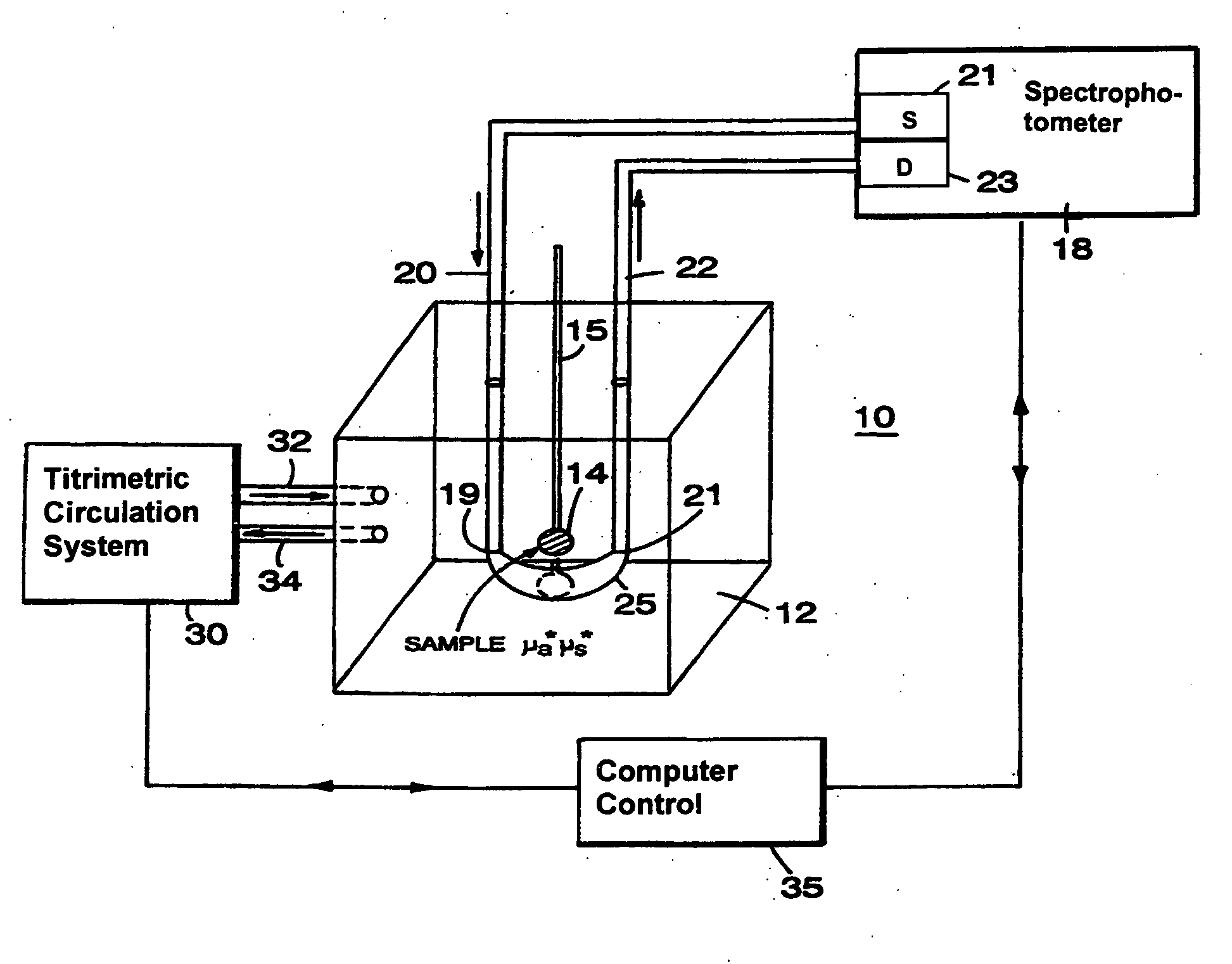
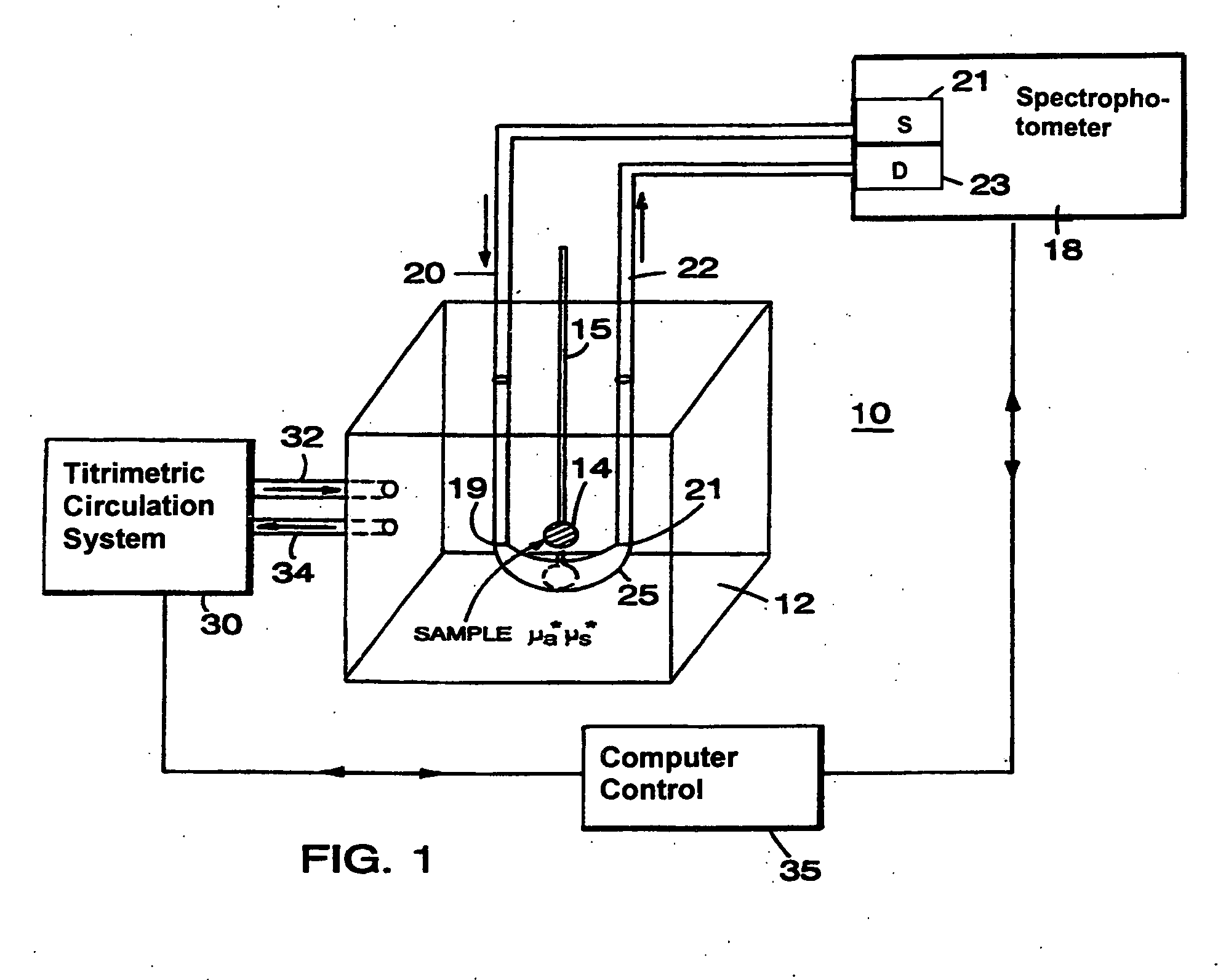
[0057]Referring to FIG. 1, the basic principle of operation of different optical couplers is explained by describing a system 10. System 10, designed for examination of biological tissue of a relatively small volume, includes an optical medium 12 of selectable optical properties, a spectrophotometer 18, a titrimetric circulation system 30, and computer control 35. Biological tissue of interest 14, attached to a locator 15, is immersed in optical medium 12. Spectrophotometer 18 examines optical properties of medium 12 by employing visible or infra-red light conducted via light guides 20 and 22. Light guides 20 and 22, which in a preferred embodiment are optical fibers, are connected to a light source 21 and a light detector 23, respectively. Photons introduced at an optical input port 19 migrate in medium 12 through a scattering and absorptive path and are detected at a detection port 21. The selectable fixed geometry of input port 19 and detection port 21 controls the migration path...


PUM

PropertyMeasurementUnit
frequencyaaaaaaaaaa
wavelengthsaaaaaaaaaa

Abstract

A spectrophotometric system for examination of biological tissue of interest includes a light source, a light coupling system, a light detector, and a processor. The light source is constructed and arranged to emit a light beam of visible or infra-red radiation. The light coupling system includes at least one mirror and is constructed and arranged to receive the emitted light beam and scan the light beam for introduction into the biological tissue of interest. The light detector is optically coupled to detect photons of radiation that have migrated over optical paths in the biological tissue of interest. The processor is operatively coupled to the light source and detector and is adapted to determine an optical property of the biological tissue of interest based on the changes between the introduced and detected radiation.

Description

BACKGROUND OF THE INVENTION[0001]Continuous wave (CW) spectrophotometers have been widely used to determine in vivo concentration of an optically absorbing pigment (e.g., hemoglobin, oxyhemoglobin) in biological tissue. The CW spectrophotometers, for example, in pulse oximetry introduce light into a finger or the ear lobe to measure the light attenuation and then evaluate the concentration based on the Beer Lambert equation or modified Beer Lambert absorbance equation. The Beer Lambert equation (1) describes the relationship between the concentration of an absorbent constituent (C), the extinction coefficient (ε), the photon migration pathlength <L>, and the attenuated light intensity (I / Io).log[I / I0]〈L〉=∑εici(1)However, direct application of the Beer Lambert equation poses several problems. Since the tissue structure and physiology vary significantly, the optical pathlength of migrating photons also varies significantly and can not be simply determined from geometrical positi...

Claims


Application Information

Patent Timeline
Patent Type & Authority Applications(United States)
IPC IPC(8): A61B6/00G01N21/64A61B5/00A61B5/145A61B5/1455A61B5/1459A61B5/1464G01N21/01G01N21/27G01N21/49
CPCA61B5/0077A61B5/0091A61B5/14532A61B5/1455A61B5/14551A61B5/14552A61B2562/146A61B5/1459A61B5/4312A61B5/6814A61B5/6853A61B2562/0233A61B2562/046A61B5/14553A61B5/0035A61B5/0042
Inventor CHANCE, BRITTON
Owner CHANCE BRITTON
Why Eureka
Try Eureka