
Modeling geologic objects in faulted formations

a geological object and fault technology, applied in seismology for waterlogging, instruments, reradiation, etc., can solve the problems of inability to support general deformation, no tool available for modeling folding after, and difficulty in defining a geological body that spans multiple block units

Active Publication Date: 2009-04-21
SCHLUMBERGER TECH CORP
View PDF4 Cites 90 Cited by
  • Summary
  • Abstract
  • Description
  • Claims
  • Application Information

AI Technical Summary

Benefits of technology

[0014]Accordingly, a system and method of modeling geological objects in volume of interest is provided. The system and method can be applied to geological objects situated in deformed regions. The system and method applies a set of paleo-transforms to a volumetric structural model and associated data representing the contemporary setting, building geological objects in the paleo-setting and applying another set of inverse paleo-transformations to the geological objects defined manually or stochastically in the paleo setting to obtain their contemporary setting and morphology and trimming the geological objects to fit in each contemporary fault block. The solution models the geological bodies in an original, e.g., unfaulted, unfolded paleo-space model obtained by applying o...

Problems solved by technology

Currently, no tool available permits modeling of folding after the deposition of the geological body, except for the FluvSim™, a fluvial simulation geostatistical package available in Modeling Office, GeoFrame 4.0™.
Defining a geological body that spans multiple block units remains tedious because the geological body must be remodeled for each block unit.
This is problematic when a three dimensional geological body has a lateral extent spanning multiple fault blocks in a three dimensional structural model.
Limited post-depositional deformation of the geological body can be captured by making the geological body shape conform to one or two controlling surfaces, but these must be single-valued height fields so general deformations are not supported in the current art.
These section views can be interpolated to provide a corresponding three dimensional paleo-space model, but such interpolation is often inaccurate, particularly with regard to strike-slip movements perpendicular to the plane of the section.
However, the transformation is not applied to faulted structural models.
Although any of these approaches is suitable for the construction of a paleo-model, none provides a mechanism for modeling of deformation after the deposition of a geological body and focused classify of the deformed body.

Method used


Image

  • Modeling geologic objects in faulted formations
  • Modeling geologic objects in faulted formations
  • Modeling geologic objects in faulted formations

Examples


Embodiment Construction

[0035]The present invention is directed to a method of modeling geological objects, or geological bodies, in regions which have experienced some sort of deformation. As used herein, the term “deformation” refers (without limitation) to folding, faulting, fracturing, shearing, compression, and / or extension. In the embodiments described below, investigations concern a formation subjected to both folding and faulting.

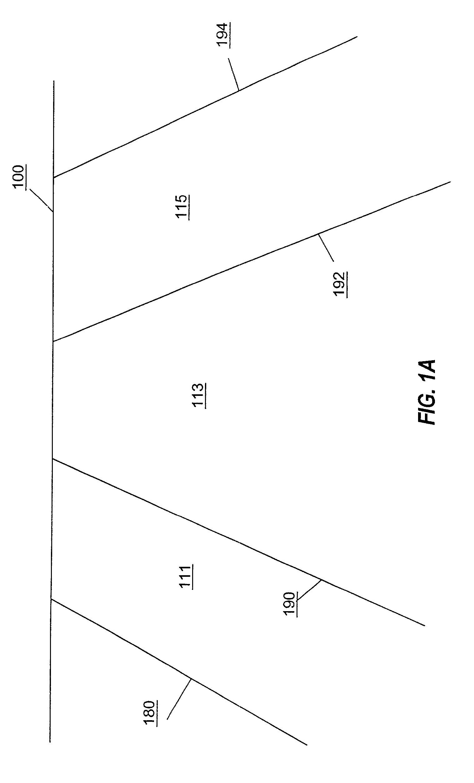
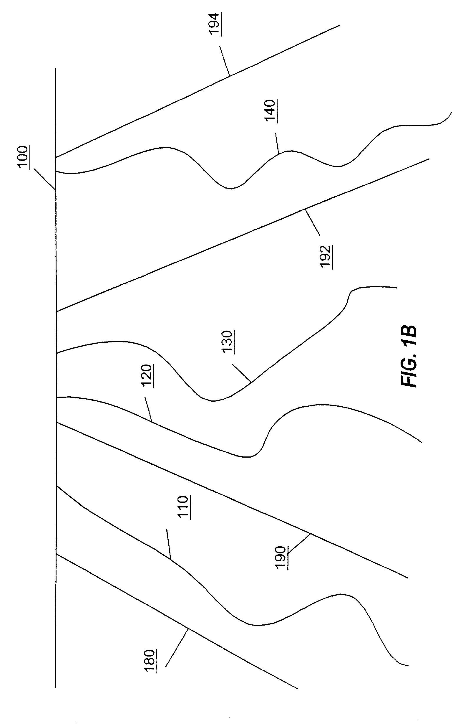
[0036]A modeling process according to an embodiment includes preparing a model as is known in the art. More particularly, referring to FIG. 1A, a formation is shown with fault lines 180, 190, 192 and 194 that are shown below a surface 100. The geological body shown in FIG. 1A can be a volume of interest (VOI) for which study is indicated. The fault lines through the VOI are said to define fault blocks 111, 113 and 115. The technique of designating fault lines through a VOI is referred to as fault splitting, wherein the faults separate the VOI into fault blocks.

[0037]The fa...


PUM


Abstract

A system and method of modeling a geological body in a contemporary formation is presented that includes constructing a geological object based on an original depositional paleo-space associated with the contemporary formation, and copying the geological object, transforming the copy of the geological object based on a deformation model of the contemporary formation using acquired data, the transforming allowing modeling of the deformed formation geological body and a lateral extent spanning a plurality of fault blocks.

Description

BACKGROUND OF THE INVENTION[0001]1. Field of the Invention[0002]The present invention generally relates to the investigation and characterization of geologic formations, and more particularly to a method and system for modeling geological objects, or geological bodies, in regions which have a deformation such as folding, faulting, fracturing, shearing, compression, or extension.[0003]2. Description of the Related Art[0004]Geologic data are used for land-management decision-making, engineering design, in the hunt for mineral resources, and for scientific research. Geologists have devised a wide variety of techniques to collect and analyze data relating to the structure and content of earth formations in the continuing search for underground assets, particularly hydrocarbons such as oil and gas. These techniques include, for example, seismic sensing, and downhole logging. In seismic sensing, a sound source is placed at the surface, or at an underground location, and an array of seismi...

Claims


Application Information

Patent Timeline
IPC IPC(8): G06G7/48G01V11/00
CPCG01V11/00G01V20/00
Inventor ENDRES, DAVID MACKBOUZAS, HORACIO R
Owner SCHLUMBERGER TECH CORP
Learn More