Fastener retention system

a fastener and retaining device technology, applied in the field of orthopedic implantable devices, can solve the problems of poor fit, lack of anatomical correspondence, susceptibility to pulling out, etc., and achieve the effect of reducing the number of required multiple configurations

Active Publication Date: 2009-04-28
ALTUS PARTNERS
View PDF14 Cites 87 Cited by
  • Summary
  • Abstract
  • Description
  • Claims
  • Application Information

AI Technical Summary

Benefits of technology

[0006]It is an object of the present invention to provide a plate system and associated method that minimizes the number of required multiple configurations and sides of hardware on hand during surgery for repair, stabilization or fusion of bone segments.

Problems solved by technology

Such shortcomings include lack of versatility so as to require multiple configurations and sizes of hardware on hand during surgery; lack of anatomical correspondence with resultant poor fit, high stress concentrations and unnatural load forces on adjacent or fused bone segments; susceptibility to pulling out due to limited arrangement of bone fastener or bone screw angles; and other shortcomings inherent to known designs.

Method used


Image

  • Fastener retention system
  • Fastener retention system
  • Fastener retention system

Examples


Embodiment Construction

[0045]The present invention system and method may be used to join a variety of bone segments for stabilization, controlled or restricted movement, and / or fusion. The present invention is particularly well-suited for use in joining vertebral bodies and, thus, is presented for use in joining cervical vertebrae in the description of the preferred embodiment. This is not intended, however, to be limiting on the scope of the present invention.

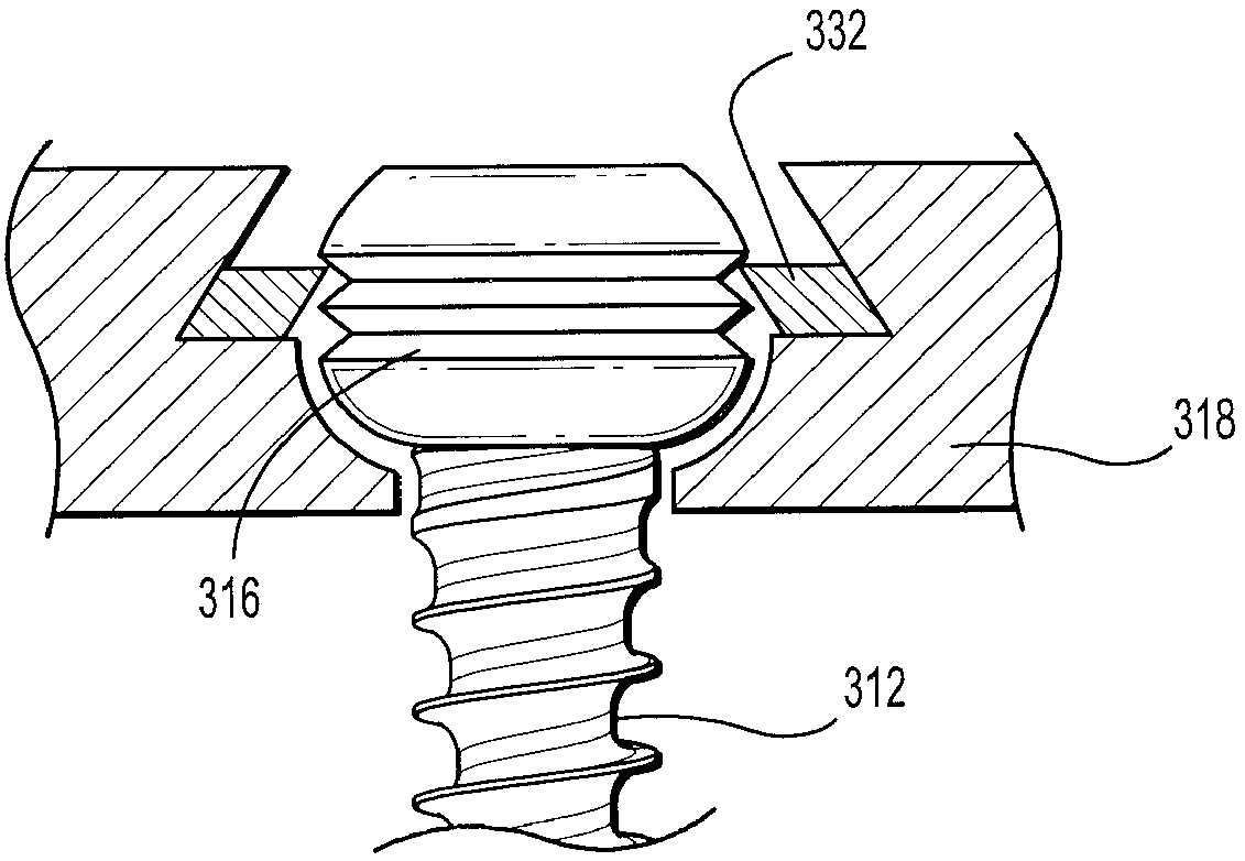
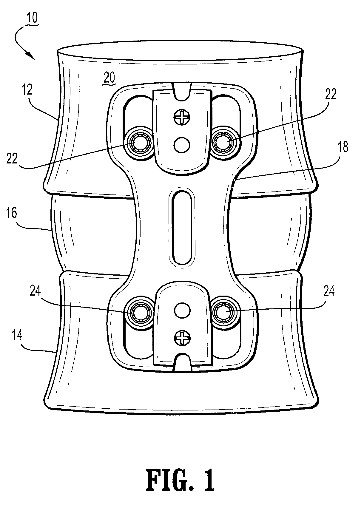
[0046]Referring to FIG. 1, there is shown schematically a group of cervical vertebral bodies (10) comprising two adjacent vertebrae (12, 14) having a disc space (16) therebetween, viewed from a side view or medial perspective. A plate (18) according to the present invention is shown fastened to the anterior side (20) of the column of vertebrae in a manner bridging across the disc space (16). Bone screws (22, 24) are used to fasten the plate in position in accordance with the present invention to stabilize the vertebrae (12, 14) for controlled moveme...


PUM


Abstract

A vertebral plate system and associated method minimizes the number of required multiple configurations and sizes of hardware on hand during surgery for repair, stabilization or fusion of bone segments. A novel aspect of the invention is a resilient split ring that cooperates with angled contact surfaces in a plate for allowing convenient and fast dynamic locking between the plate and a bone screw. In another aspect of the present invention, a screw or similarly elongated fastener having a generally spherical or part-spherical head with a section of helical threads is configured in a generally horizontal band and positioned around a maximum-diameter section of the head. The screw is loosely retained to a first structure by a snap-ring formed from a ring of elastic material having a slot cut so that the ring is a “C” ring. The ring is seated on an annular shoulder formed in a through-hole in the first structure. The section of the through-hole above the shoulder tapers inwardly in an upward direction to a minimum diameter that is smaller than the outside diameter of the ring when the ring is in an unstressed state. The inner diameter of the ring has an edge that is adapted to cooperate with and ride in the threads on the screw head.

Description

RELATED APPLICATIONS[0001]This application is related to, and claims priority from, the following earlier-filed U.S. Provisional Patent Applications: (Serial Nos.) 60 / 422,978 (filed 04 Nov. 2002); 60 / 479,797 (filed 20 Jun. 2003); and 60 / 476,642 (filed 09 Jun 2003). Each is incorporated herein by reference.TECHNICAL FIELD[0002]The present invention relates to orthopedic implantable devices, related systems, and associated methods of use and, more particularly, to a plate system and associated method for joining two or more bone segments, such as vertebrae.BACKGROUND OF THE INVENTION[0003]In orthopedics it is known to use various types of plates fastened to one or more bone segments in order to join said bone segments in a predetermined relationship for stabilization and / or controlled movement. Such stabilization or controlled movement is desirable when repairing bone segments that have become deteriorated, damaged or degenerative, such as due to trauma or disease. Such stabilization ...

Claims


Application Information

Patent Timeline
Patent Type & Authority Patents(United States)
IPC IPC(8): A61B17/80A61B17/70
CPCA61B17/7059A61B17/8042A61B17/8047
Inventor KHALILI, FARID BRUCE
Owner ALTUS PARTNERS
Why Eureka
Try Eureka