Modular filter assembly

a filter and module technology, applied in the field of filters, can solve the problems of increasing the cost of the filter, reducing the efficiency of the filter,

Inactive Publication Date: 2009-04-28
WHIRLPOOL CORP
View PDF17 Cites 39 Cited by
  • Summary
  • Abstract
  • Description
  • Claims
  • Application Information

AI Technical Summary

Benefits of technology

[0014]The keyed connection can be provided between the insert opening and the air treatment medium to control the size of the air treatment medium relative to the insert opening.
[0016]The frame can have an inlet opening providing access to the interior space and the air treatment medium can be sized to be inserted through the inlet opening. A keyed connection between the frame and the air treatment medium can control the engagement of the air treatment medium with the frame. The frame can be sized to be slidably inserted into a standardized opening in the air duct.

Problems solved by technology

Although these filters are able to capture large particles, they do little to remove smaller particles from the air.
HEPA filters efficiently remove submicron particles, but they are relatively expensive and create a higher pressure drop.
Washable fiberglass filters cannot be completely cleaned to their original state and, therefore, can restrict airflow.
Other than size differentiation, conventional filter configurations do not prevent the installation of an inappropriate filter in the HVAC system.

Method used


Image

  • Modular filter assembly
  • Modular filter assembly
  • Modular filter assembly

Examples


first embodiment

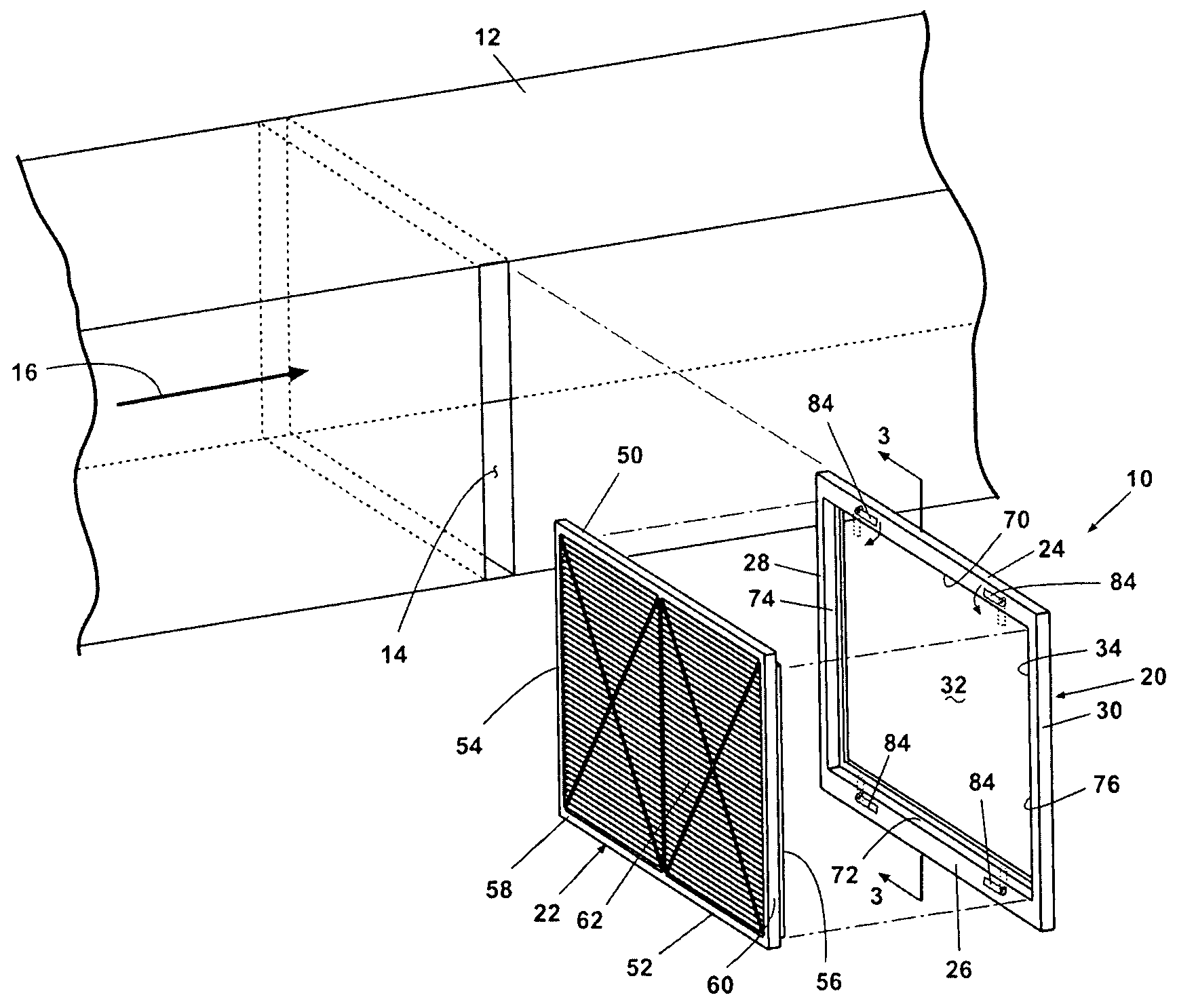
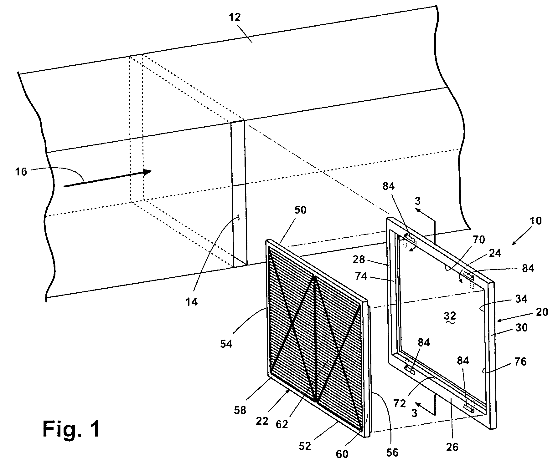
[0040]FIG. 3 best illustrates the keyed connection 36 in which the top rail 24 as an inwardly-directed top rail edge 70, and the bottom rail 26 has an inwardly-directed bottom rail edge 72. The stile 28 has an inwardly-directed stile edge 74, and the stile 30 has an inwardly-directed stile edge 76. The edges 70-76 define a perimeter 78 having a perimeter rabbet 80 extending therealong. The perimeter rabbet 80 defines a flange seat 82.

[0041]The air treatment medium 22 terminates along the perimeter 58 in a perimeter flange 60 having dimensions complementary to the perimeter rabbet 80 and which defines a rectilinear central portion 62 having perimetric dimensions complementary to the dimensions of the interior space 32 of the frame 20. The air treatment medium 22 is brought into slidable registry with the frame 20 by inserting the central portion 62 into the interior space 32 so that the perimeter flange 60 is in registry with the flange seat 82. An array of suitable, well-known retai...

second embodiment

[0044]FIG. 4 illustrates the keyed connection 36 in which the inner frame perimeter 90 has a perimeter bevel 92 comprising the key 38, and the filter medium outer perimeter 94 has a perimeter bevel 96 comprising the keyway 40 complementary to the perimeter bevel 92. The bevels 92, 96 are adapted so that the air treatment medium 22 can be inserted into the interior space 32 to bring the bevels 92, 96 into registry and prevent further insertion of the air treatment medium 22 into the frame 20. The air treatment medium 22 can be removably retained in the frame 20 by an array of suitable retaining devices 84, as previously described.

third embodiment

[0045]FIG. 5 illustrates the keyed connection 36 in which the frame 20 is provided with an array of filter posts 100 and the air treatment medium 22 is provided with an array of support apertures 102 complementary to the filter posts 100. Preferably, the filter posts 100 extend orthogonally away from the plane of the frame 20 along an outer edge thereof, and the support apertures 102 extend through the air treatment medium 22 along an outer edge thereof, for slidable insertion of the filter posts 100 into the support apertures 102. The air treatment medium 22 can be removably retained in the frame 20 by an array of suitable retaining devices 84, as previously described, or by adapting the filter posts 100 and the support apertures 102 for an interference fit of the filter posts 100 with the support apertures 102.

[0046]FIG. 6A illustrates an embodiment of the keyed connection 36 comprising an air treatment medium 110 pre-configured with frame elements. The pre-configured frame elemen...


PUM

PropertyMeasurementUnit
sizeaaaaaaaaaa
sizeaaaaaaaaaa
humidityaaaaaaaaaa

Abstract

An air treatment assembly for treating air passing through an air duct comprises a frame defining an interior space and having an inlet opening providing access to the interior space, an air treatment medium sized to be inserted into the interior space through the inlet opening, and a keyed connection between the frame and the air treatment medium to control the engagement of the air treatment medium with the frame. The air treatment assembly also comprises a frame defining an interior space, an air treatment medium sized to be received within the interior space, and an air quality module integrated with the frame.

Description

BACKGROUND OF THE INVENTION[0001]1. Field of the Invention[0002]The invention relates generally to filters for filtering fluids, such as air. In one aspect, the invention relates to a filter assembly comprising a modular frame supporting a uniquely communicating filter medium. In another aspect, the invention relates to a filter assembly comprising a frame supporting a filter medium and a fluid quality module.[0003]2. Description of the Related Art[0004]Conventional forced air furnaces or central air conditioners (generically referred to as heating, ventilating, and air conditioning, or HVAC, systems) comprise a return air duct to direct air into a central unit for conditioning by either heating or cooling, and an outlet duct for distribution of the conditioned air from the central unit throughout the building. The return air duct typically has a filter disposed therein for removing dust and other particulate matter from the incoming air. As air passes through the filter, the matter...

Claims


Application Information

Patent Timeline
Patent Type & Authority Patents(United States)
IPC IPC(8): B01D46/00
CPCB01D46/0005B01D46/009B01D46/10B01D46/521B01D2265/028Y10S55/31
Inventor WU, GUOLIANLITCH, ANDREW D.KARP, ALEXANDER J.
Owner WHIRLPOOL CORP
Why Eureka
Try Eureka