Optical apparatus having a driving source for driving a lens in an optical axis direction

a technology of optical axis and driving source, which is applied in the direction of mountings, instruments, and electromechanical/electrostrictive/magnetostrictive devices, etc., can solve the problems of increasing the driving load, increasing the output power of vibration type linear actuators, and wear of engagement parts

Inactive Publication Date: 2009-04-28
CANON KK
View PDF17 Cites 2 Cited by
  • Summary
  • Abstract
  • Description
  • Claims
  • Application Information

AI Technical Summary

Benefits of technology

[0008]It is an object of the present invention to provide an optical apparatus in which a press contact force for bringing a vibrator and a contact member into press contact with each other is generated between them to make the reaction force of the press contact force difficult to be transmitted to the outside of the vibrator and contact member.

Problems solved by technology

The press contact force in the vibration type linear actuator is extremely large, so that such a lateral pressure increases the friction in the engagement part, thereby increasing the driving load.
This causes problems that an increase of the output power of the vibration type linear actuator is required, the engagement part is worn, and it becomes difficult to perform a fine and accurate lens drive.

Method used


Image

  • Optical apparatus having a driving source for driving a lens in an optical axis direction
  • Optical apparatus having a driving source for driving a lens in an optical axis direction
  • Optical apparatus having a driving source for driving a lens in an optical axis direction

Examples


embodiment 1

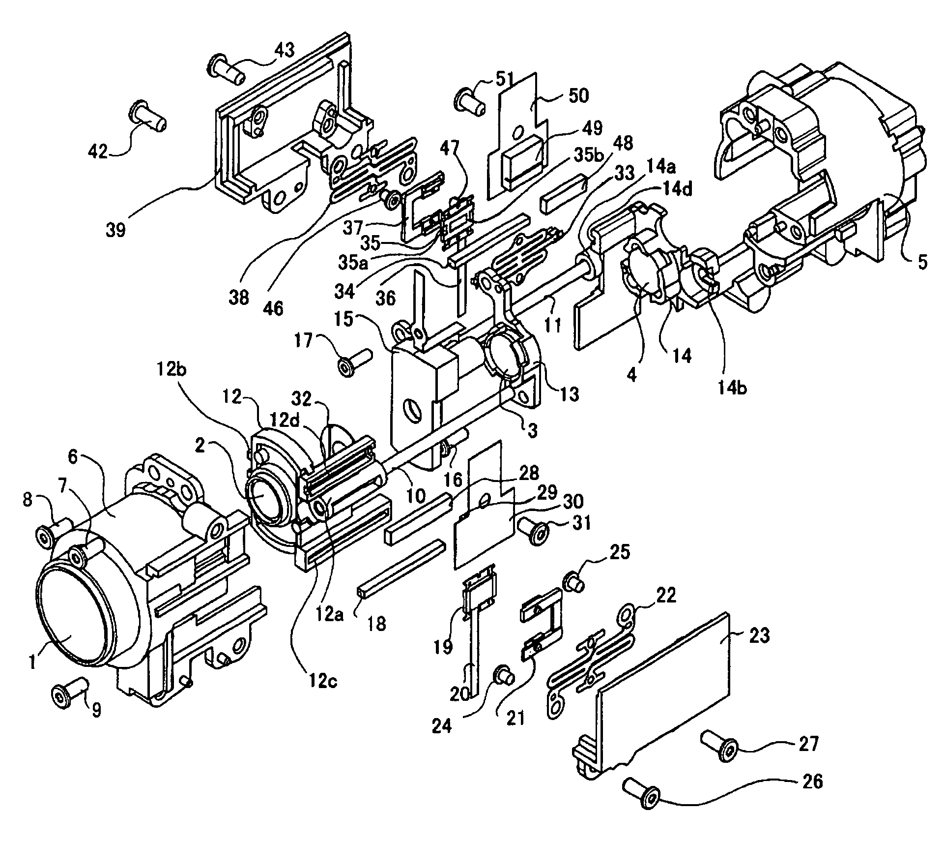
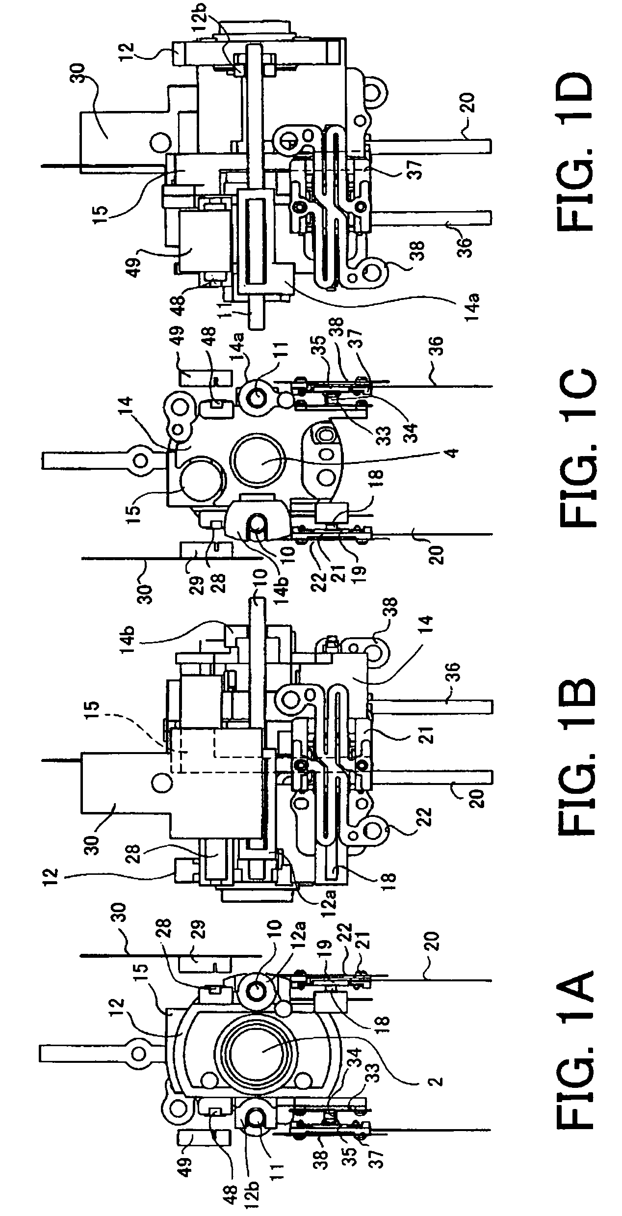
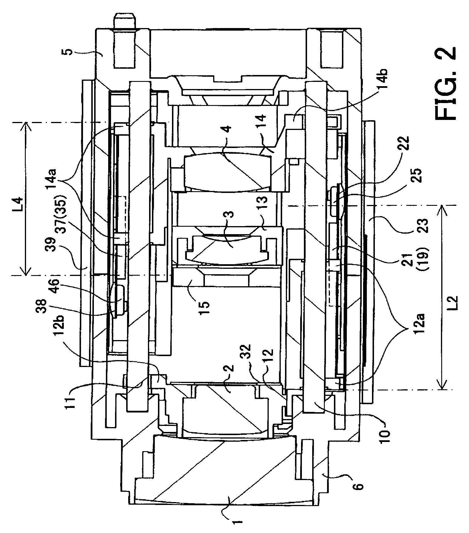
[0033]FIGS. 1A to 1D show a lens barrel, with its exterior removed, in an image-taking apparatus (optical apparatus) which is Embodiment 1 of the present invention when viewed from four directions, the front, right, back, and left, respectively. FIG. 2 is a section view of the lens barrel taken along the plane including the optical axis of the lens barrel. FIG. 3 is an exploded perspective view of the lens barrel. FIGS. 4A and 4B are partial enlarged views showing a vibration type linear actuator for driving a second lens unit which forms part of the lens barrel. FIGS. 5A and 5B are partial enlarged views showing a vibration type linear actuator for driving a fourth lens unit which forms part of the lens barrel. FIG. 5C schematically shows the structure of a light amount adjusting unit which forms part of the lens barrel. FIG. 6 shows the electrical structure of the image-taking apparatus of Embodiment 1.

[0034]In FIGS. 1A to 6, in order from an object side, reference numerals 1 show...

embodiment 2

[0071]FIGS. 7 to 10 show the structure of a lens barrel of an image-taking apparatus which is Embodiment 2 of the present invention. FIG. 7 shows a section view of the lens barrel in Embodiment 2 taken along a plane in parallel with an optical axis and perpendicular to a press contact surface between a slider and vibrator of a vibration type linear actuator. FIG. 8 shows a section view of the lens barrel in Embodiment 2 taken along a plane perpendicular to the optical axis and perpendicular to a press contact surface of a vibration type linear actuator for driving a second lens unit when viewed from an object side. FIG. 9 shows a section view of the lens barrel in Embodiment 2 taken along a plane perpendicular to the optical axis and perpendicular to a press contact surface of a vibration type linear actuator for driving a fourth lens unit when viewed from the object side. FIG. 10 is an exploded view showing the lens barrel in Embodiment 2. The image-taking apparatus of Embodiment 2...

embodiment 3

[0107]FIGS. 11A to 15 show the structure of a lens barrel of an image-taking apparatus which is Embodiment 3 of the present invention. FIGS. 11A to 11D show the lens barrel in Embodiment 3, with its exterior removed, when viewed from four directions, the right, back, left, and front, respectively. FIG. 12 shows a section view of the lens barrel in Embodiment 3 taken along a plane in parallel with an optical axis and perpendicular to a press contact surface between a slider and a vibrator of a vibration type linear actuator. FIG. 13 shows a section view of the lens barrel in Embodiment 3 taken along a plane perpendicular to the optical axis and perpendicular to a press contact surface of a vibration type linear actuator for driving a second lens unit when viewed from an object side. FIG. 14 shows a section view of the lens barrel in Embodiment 3 taken along a plane perpendicular to the optical axis and perpendicular to a press contact surface of a vibration type linear actuator for d...


PUM


Abstract

An optical apparatus is disclosed in which a press contact force for bringing a vibrator and a contact member into press contact with each other is generated between them, and thereby the reaction force of the press contact force is difficult to transmit outward. The optical apparatus comprises a lens holding member which holds a lens, and a vibration type linear actuator which drives the lens holding member in an optical axis direction. The vibration type linear actuator includes a vibrator on which vibration is produced through an electromechanical energy conversion action and a contact member which is in press contact with the vibrator. The vibrator and the contact member is in press contact with each other by a magnetic force acting between them.

Description

BACKGROUND OF THE INVENTION[0001]The present invention relates to an optical apparatus having a driving source for driving a lens in an optical axis direction, and particularly, to an optical apparatus which includes a vibration type linear actuator for use as a driving source.[0002]Some optical apparatuses include a vibration type linear actuator for use as a driving source for driving a lens (for example, see Japanese Patent Laid-Open No. 10(1998)-90584).[0003]In the optical apparatuses proposed in Japanese Patent Laid-Open No. 10(1998)-90584 having the vibration type linear actuator, the vibration type linear actuator is formed of a vibrator which produces vibration through an electromechanical energy conversion action and a contact member which is in press contact with the vibrator. The vibrator is fixed to a lens holding member, the contact member is fixed to a stationary member of a lens barrel, and the vibrator is caused to produce driving vibration, thereby moving the lens h...

Claims


Application Information

Patent Timeline
Patent Type & Authority Patents(United States)
IPC IPC(8): H01L41/00G02B7/04
CPCG02B7/022G02B7/023
Inventor NAKASHIMA, SHIGEOSATO
Owner CANON KK
Why Eureka
Try Eureka