Electrodeless discharge lamp and lighting apparatus using the same
- Summary
- Abstract
- Description
- Claims
- Application Information
AI Technical Summary
Benefits of technology
Problems solved by technology
Method used
Image
Examples
first embodiment
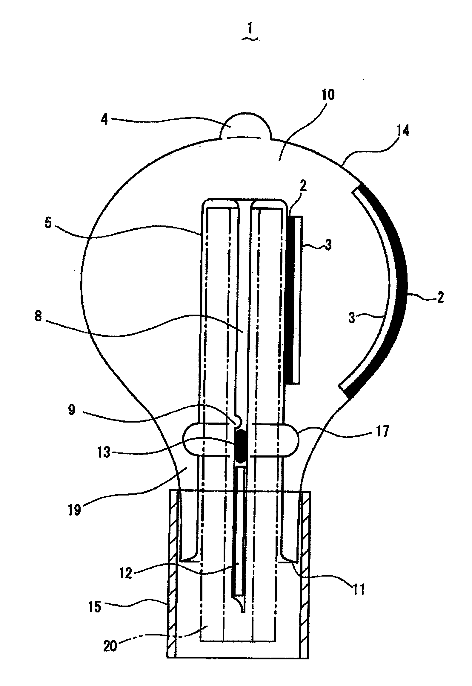
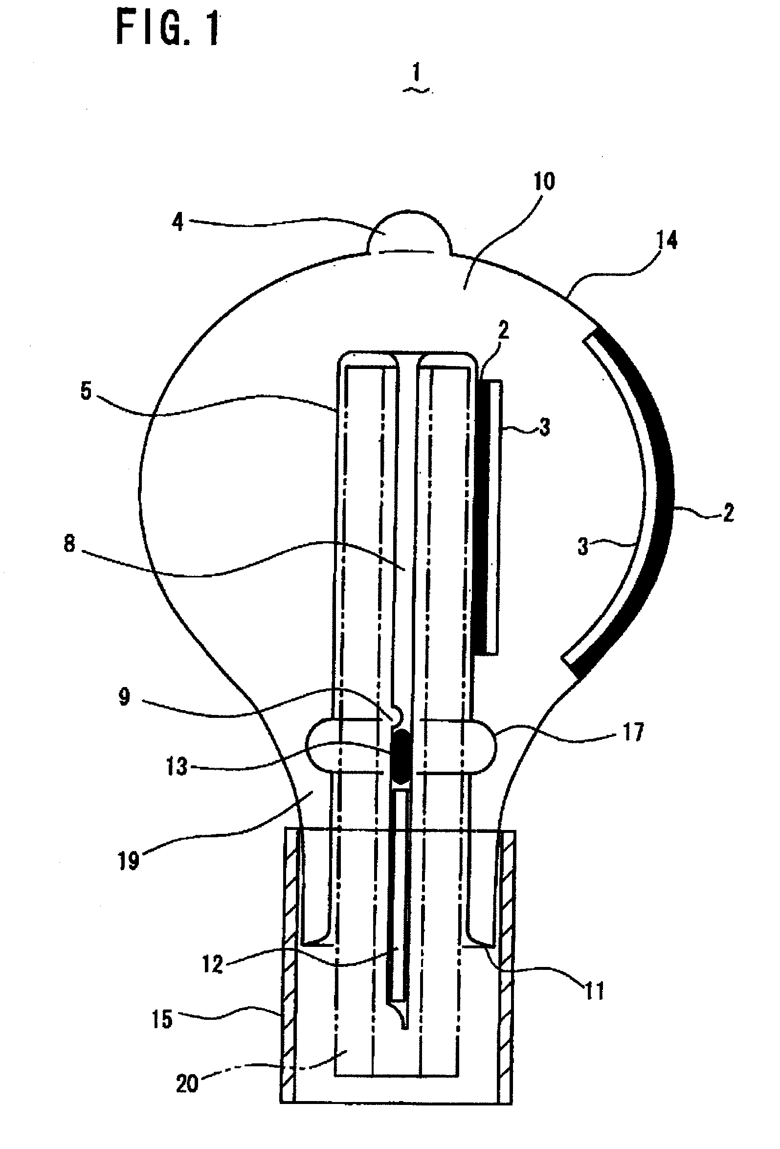
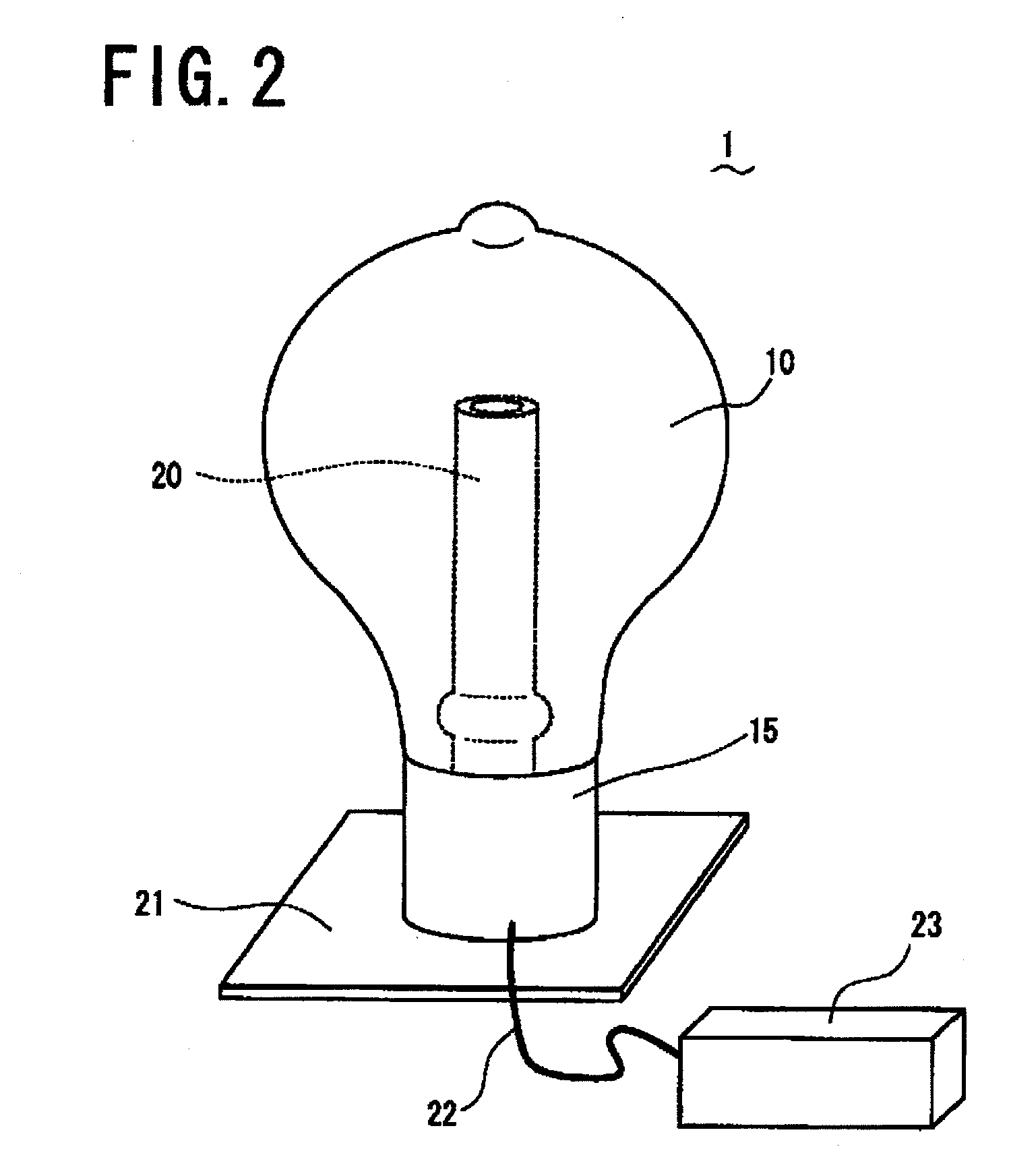
[0020]At first, an electrodeless discharge lamp in accordance with a first embodiment of the present invention is described. FIG. 1 shows a configuration of an electrodeless discharge lamp according to the first embodiment. The electrodeless discharge lamp 1 according to the first embodiment comprises a bulb 10 into which discharge gas and mercury which is controlled with temperature of the coldest spot, and a power coupler 20 which generates high frequency electromagnetic field. The bulb 10 is a hermetic container configured of a substantially spherical barrel 14 formed of a transparent material and having a circular opening, and a sealing member 11 welded to the circular opening of the barrel 14 and having a substantially cylindrical cavity 5 and an exhaust tube 8 formed at a center portion of the cavity 5. As illustrated by two-dotted chain line in FIG. 1, the power coupler 20 is configured of an induction coil for generating an induction field and a ferrite core, and engaged wit...
second embodiment
[0030]Subsequently, an electrodeless discharge lamp in accordance with a second embodiment of the present invention is described. FIG. 3 shows a configuration of an electrodeless discharge lamp according to the second embodiment. Since the portions, to which the same codes as those of the electrodeless discharge lamp according to the first embodiment shown in FIG. 1 are applied, are substantially the same, description of them is omitted.
[0031]In the second embodiment shown in FIG. 3, an annular protruding portion 16, which protrudes outward along the circumferential direction of the barrel 14 constituting the bulb 10, is formed in the vicinity of the sealing portion of the bulb 10, that is, just above the ferrule 15 when the ferrule 15 is disposed upward. In this way, since the protruding portion 16 is formed to protrude outward of the bulb 10, an inside concavity of the protruding portion 16 is positioned away from a portion where discharge actually occurs, and thus, heat generated...
third embodiment
[0034]Subsequently, an electrodeless discharge lamp in accordance with a third embodiment of the present invention is described. FIG. 5 shows a configuration of an electrodeless discharge lamp according to the third embodiment. In FIG. 5, the power coupler 20 to be fit into the cavity 5 is also illustrated by solid lines. In addition, since the portions, to which the same codes as those of the electrodeless discharge lamp according to the first embodiment shown in FIG. 1 or the second embodiment show in FIG. 3 are applied, are substantially the same, description of them is omitted.
[0035]As shown in FIG. 5, the bulb 10 in the third embodiment possesses the annular protruding portion 17 formed along the outer peripheral face of the cavity 5 which is the characteristic of the first above embodiment and the annular protruding portion 16 formed along the circumferential direction of the barrel 14 which the characteristic of the second embodiment. Furthermore, spring members 18, which are...
PUM
 Abstract
Description
Claims
Application Information
 - R&D
- Intellectual Property
- Life Sciences
- Materials
- Tech Scout
- Unparalleled Data Quality
- Higher Quality Content
- 60% Fewer Hallucinations
Browse by: Latest US Patents, China's latest patents, Technical Efficacy Thesaurus, Application Domain, Technology Topic, Popular Technical Reports.
© 2025 PatSnap. All rights reserved.Legal|Privacy policy|Modern Slavery Act Transparency Statement|Sitemap|About US| Contact US: help@patsnap.com


