Shunt regulation apparatus, systems, and methods

a technology of shunt and control apparatus, applied in the direction of dynamo-electric converter control, door/window protection device, multiple dynamo-motor starters, etc., can solve the problems of sudden changes in supply voltage and unwanted heating in the vicinity of the area

Inactive Publication Date: 2009-04-28
HALLIBURTON ENERGY SERVICES INC
View PDF46 Cites 65 Cited by
  • Summary
  • Abstract
  • Description
  • Claims
  • Application Information

AI Technical Summary

Problems solved by technology

Thus, abruptly changing mechanical loads may result in correspondingly abrupt changes in supply voltage, both to the motor, and to instrumentation powered by, or derived from, the same supply.
However, such shunt regulators may operate to cause unwanted heating near the area in the downhole tool where shunting occurs.

Method used


Image

  • Shunt regulation apparatus, systems, and methods
  • Shunt regulation apparatus, systems, and methods
  • Shunt regulation apparatus, systems, and methods

Examples


Embodiment Construction

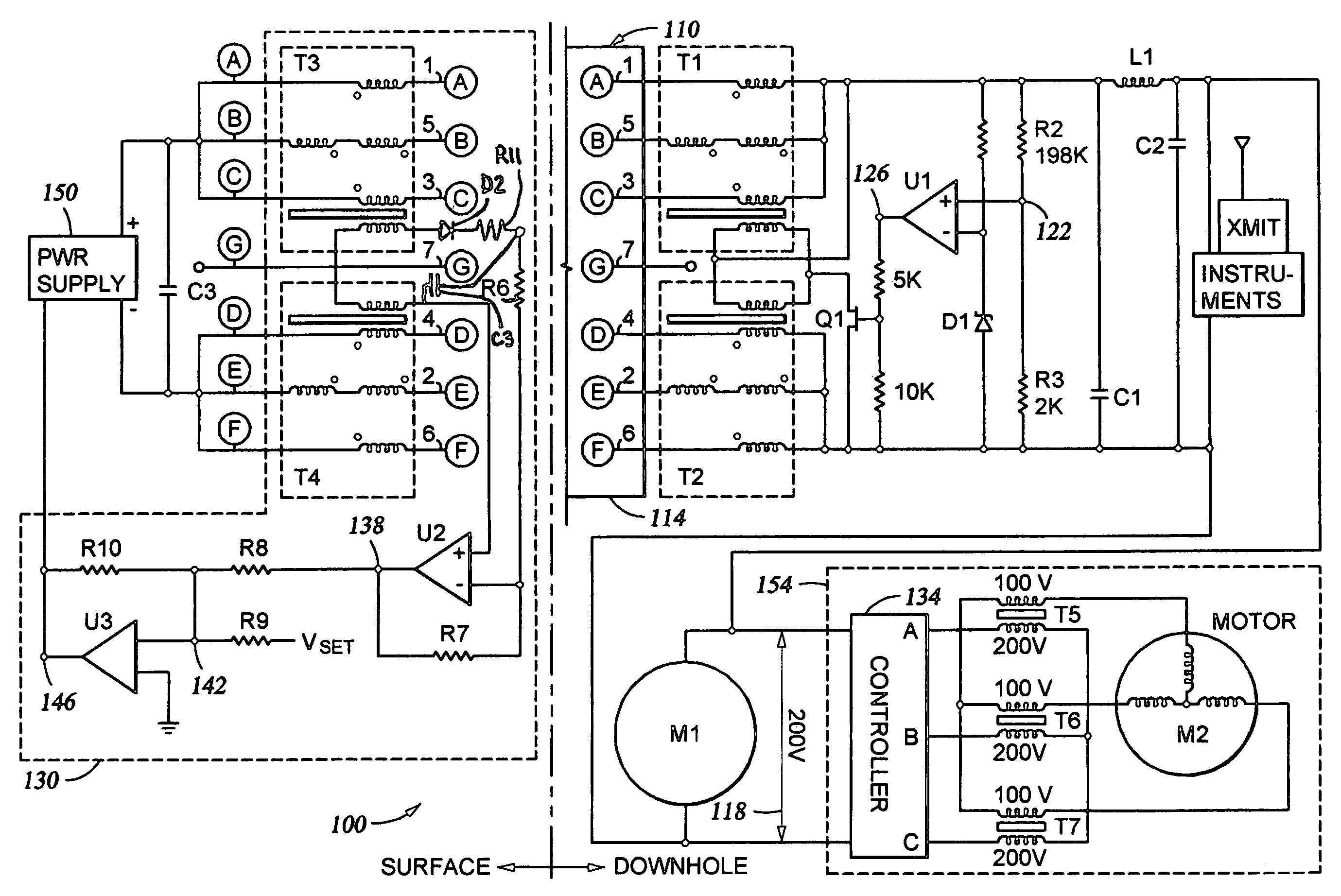
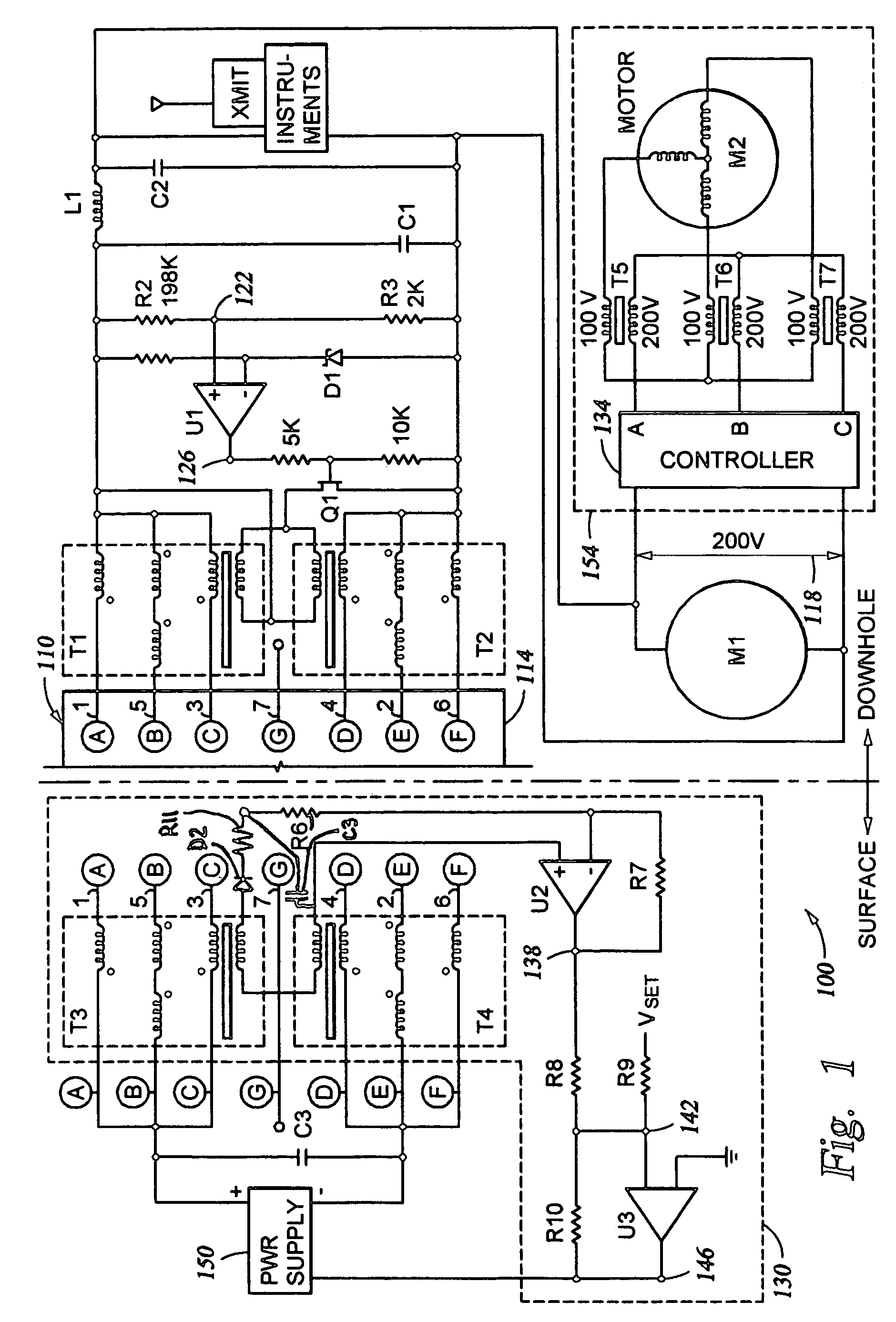
[0008]In some embodiments, a shunt voltage regulator apparatus is disclosed that can dissipate excess power into conductors connected to a load, such as a motor connected to the conductors including in a logging line cable. For example, if a cable including one or more conductors can dissipate 0.5 watts per meter, and the cable is 4000 meters long, then approximately 2000 watts may be dissipated along the cable length. In many circumstances, this constitutes a significant amount of power, and in fact, it is anticipated that even greater amounts of power may be dealt with in the same fashion.

[0009]In order to direct unwanted current into selected conductors, the current not needed by the electrical load (e.g., a motor when suddenly relieved of a mechanical load) can be shunted through the primary winding of a mode transformer. Thus, one or more mode transformers can be connected to transfer the shunted current so as to circulate in selected conductors, such as downhole logging line c...


PUM


Abstract

In some embodiments, an apparatus and a system, as well as a method and an article, may include receiving shunt current in one or more conductors according to a sensed component of power distributed by the conductors through one or more transformers coupled to the conductors and determined by an inductance associated with the transformers and a capacitance associated with the conductors.

Description

TECHNICAL FIELD[0001]Various embodiments described herein relate to electrical power management generally, including apparatus, systems, and methods for regulating current and voltage.BACKGROUND INFORMATION[0002]Motors can be used in boreholes to carry out many tasks, including operating hydraulic motors, rotating coring tool hole cutting saws, and opening / closing caliper arms. When powered near the end of a long cable, the voltage drop across the wires carrying current to the motor can be significant, since motors may use current in proportion to the mechanical loads they support. Thus, abruptly changing mechanical loads may result in correspondingly abrupt changes in supply voltage, both to the motor, and to instrumentation powered by, or derived from, the same supply.[0003]Generally, shunt regulators may be used to help regulate downhole supply voltages as motor loads change. However, such shunt regulators may operate to cause unwanted heating near the area in the downhole tool w...

Claims


Application Information

Patent Timeline
Patent Type & Authority Patents(United States)
IPC IPC(8): H02P1/54
CPCH02P1/54
Inventor DODGE, CARL
Owner HALLIBURTON ENERGY SERVICES INC
Why Eureka
Try Eureka