Spread spectrum power converter with duty-cycle error compensation

a technology of duty-cycle error compensation and power converter, which is applied in the direction of power conversion systems, dc-dc conversion, instruments, etc., to achieve the effect of avoiding accumulation errors, minimizing duty-cycle errors, and minimizing the magnitude of duty-cycle errors

Inactive Publication Date: 2009-04-28
BAYVIEW VENTURES
View PDF4 Cites 39 Cited by
  • Summary
  • Abstract
  • Description
  • Claims
  • Application Information

AI Technical Summary

Benefits of technology

[0013]For example, a pulse train can sequence through a series of different cycle durations, e.g., chosen to provide a favorable noise signature. For each cycle other than the first, the pulse duration can be chosen as a function of the target average duty cycle, the respective cycle duration, and error accumulated from one or more prior cycles, e.g., to minimize the expected accumulator error by the end of the current pulse train sequence.
[0016]The present invention recognizes that duty-cycle error compensation can be effected between the very different cycle durations that can occur in a spread-spectrum pulse train. While it does not preclude some use of dithering, the present invention does recognize that dithering is not necessary to achieve greater than nominal precision on a time-averaged basis in a spread-spectrum power converter. Thus, there is no need to compromise an ideal pulse train for noise signature purposes to permit dithering. Instead, the present invention allows the pulse train to be optimized for a desired noise signature.
[0017]The present invention provides for further enhancements to minimize the magnitudes of the duty-cycle errors that must be compensated. For example, instead of sequencing through a fixed set of cycle durations, cycle durations can be chosen to minimize duty cycle errors. For example, if the target average duty cycle is 50%, then an even cycle duration can be selected to avoid accumulating error. If there is accumulated error to compensate, an even or odd cycle duration can be selected depending on which achieves more effective compensation. By minimizing the magnitude of duty-cycle errors, noise can be further reduced. These and other features and advantages of the invention are apparent from the description below with reference to the following drawings.

Problems solved by technology

In general, the duty cycle for a pulse cycle will not match the target average duty cycle; the difference is a duty-cycle error.

Method used


Image

  • Spread spectrum power converter with duty-cycle error compensation
  • Spread spectrum power converter with duty-cycle error compensation
  • Spread spectrum power converter with duty-cycle error compensation

Examples


Embodiment Construction

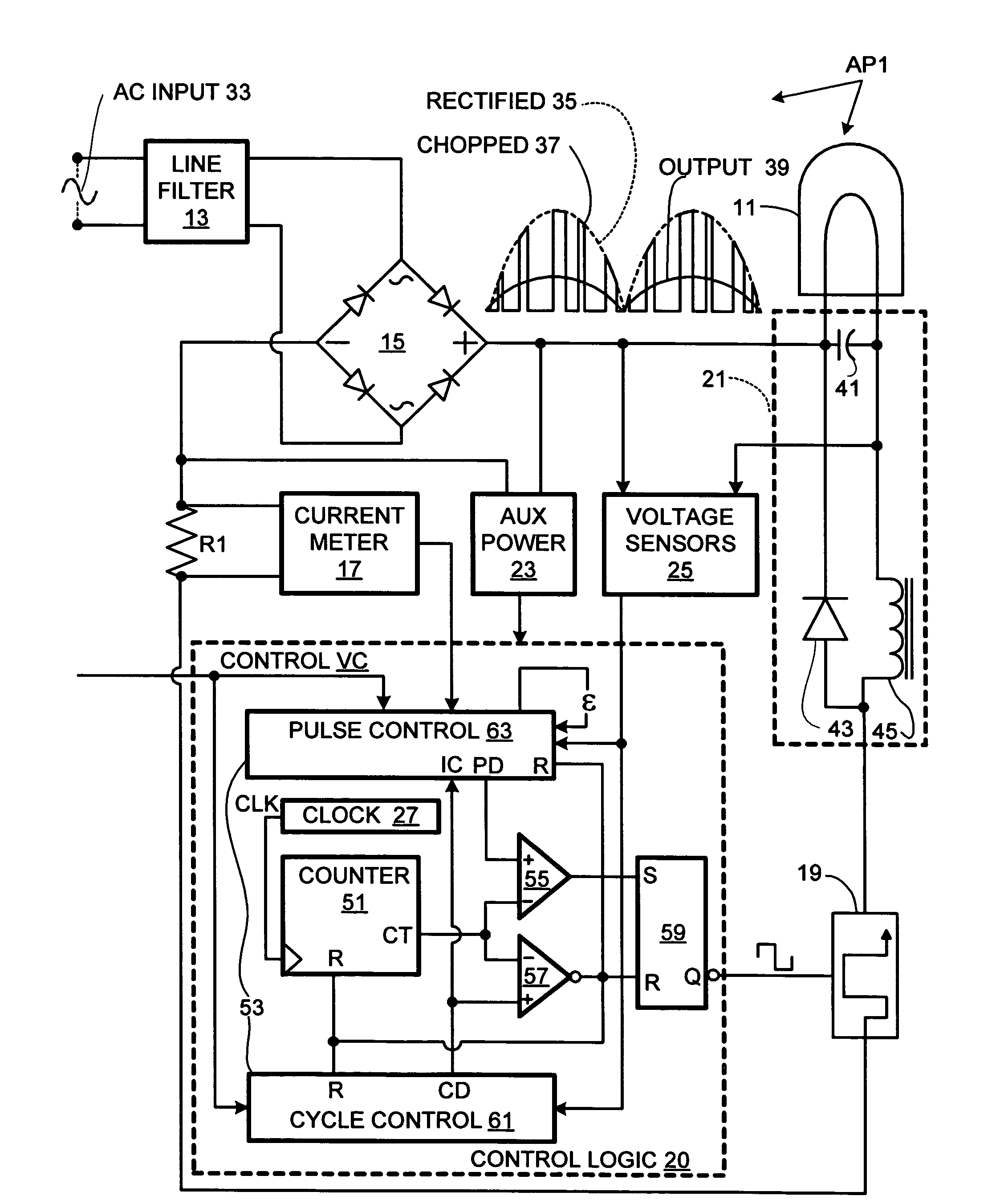
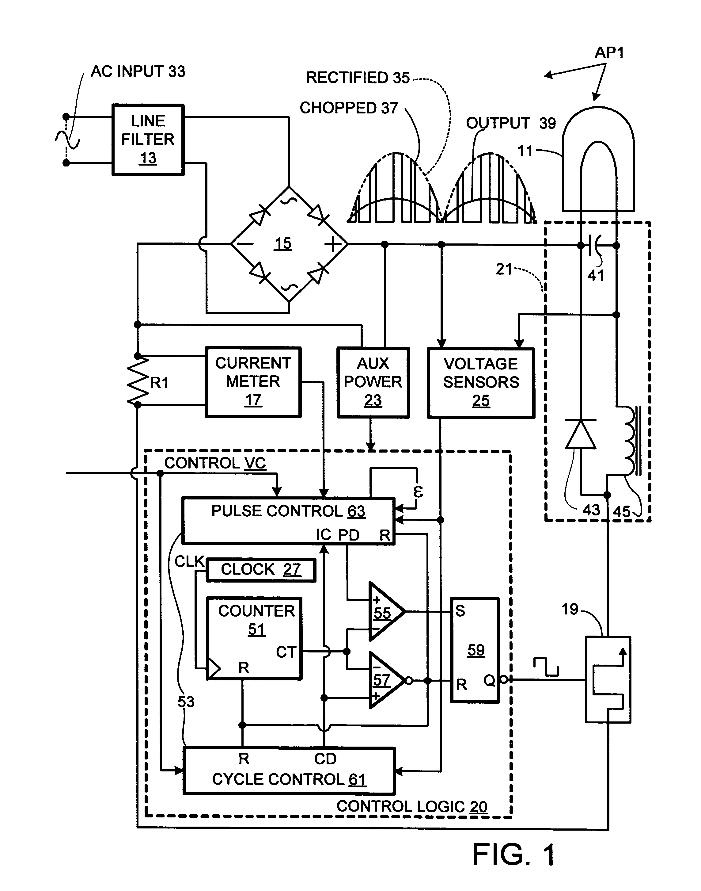
[0020]A spread-spectrum, frequency-hopping, power converter AP1, in accordance with the present invention, rectifies an input AC waveform, chops the rectified waveform, and integrates the chopped waveform to yield a periodic DC voltage waveform, which is used to drive an incandescent lamp 11, as shown in FIG. 1. The amplitude of the DC voltage waveform is controlled in response to a voltage control signal VC. This voltage control signal can be set manually, as with a dimmer control, or be based on feedback in a self-regulated system.

[0021]Power converter AP1 is implemented in an AT90PWM2 8-bit microcontroller (available from Atmel Corporation, San Jose, Calif.), which has built-in pulse-width modulation capability. Alternatively, another microcontroller with PWM capability or an external peripheral with PWM capability can be used. For explanatory purposes, power converter AP1 is described in terms of discrete components.

[0022]As shown in FIG. 1, power converter AP1 comprises an line...


PUM


Abstract

A spread-spectrum power converter uses an inter-cycle duty-cycle error compensation to achieve a combination of high-precision tracking of a target average duty cycle and a favorable noise signature. The pulse train consists of a series of cycles having cycle durations of a positive integer of clock cycles, pulse durations of a whole number of clock cycles, and duty cycles corresponding to a ratio of pulse durations over cycle durations. The pulse durations are selected at least in part as functions of a target average duty cycle, the respective cycle durations, and a ripple (or other) error from other cycles in the train. The cycle durations can also be in part a function of the target average duty cycle so that the duty cycle errors can be minimized.

Description

BACKGROUND OF THE INVENTION[0001]The present invention relates to electrical devices and, more particularly, to power converters. A major objective of the present invention is to provide a high-precision spread-spectrum power converter. Herein, related art labeled “prior art” is admitted prior art; related art not labeled “prior art” is not admitted prior art.[0002]There are many applications for power converters that require high precision control of a fixed output voltage. These are often traditional power supply applications, well know to those familiar with prior art. However, recent technology requirements have evolved requiring high precision control of variable output power converters, and more recently digitally controlled variable output power converters. When a digital control requirement is combined with a requirement for a variable output power controller, many limitations of prior art become evident. The present invention addresses these limitations with a novel control...

Claims


Application Information

Patent Timeline
Patent Type & Authority Patents(United States)
IPC IPC(8): G05F1/56
CPCH02M3/156H02M7/2176
Inventor BILLIG, RICHARD R.SCHANIN, DAVID J.
Owner BAYVIEW VENTURES
Why Eureka
Try Eureka