Resistivity logging tool and method for building the resistivity logging tool

a technology of resistivity and logging tool, which is applied in the direction of instruments, borehole/well accessories, surveys, etc., can solve the problems of inconvenient use of resistivity logging tools, inability to resolve resistivity variations around the wellbore, and inability to configure typical induction and propagation tools to resolve resistivity variations

a technology of resistivity and logging tool, which is applied in the direction of instruments, borehole/well accessories, surveys, etc., can solve the problems of inconvenient use of resistivity logging tools, inability to resolve resistivity variations around the wellbore, and inability to configure typical induction and propagation tools to resolve resistivity variations

US7525315B2Inactive Publication Date: 2009-04-28SCHLUMBERGER TECH CORP

Image

  • Resistivity logging tool and method for building the resistivity logging tool
  • Resistivity logging tool and method for building the resistivity logging tool
  • Resistivity logging tool and method for building the resistivity logging tool

Examples


Embodiment Construction

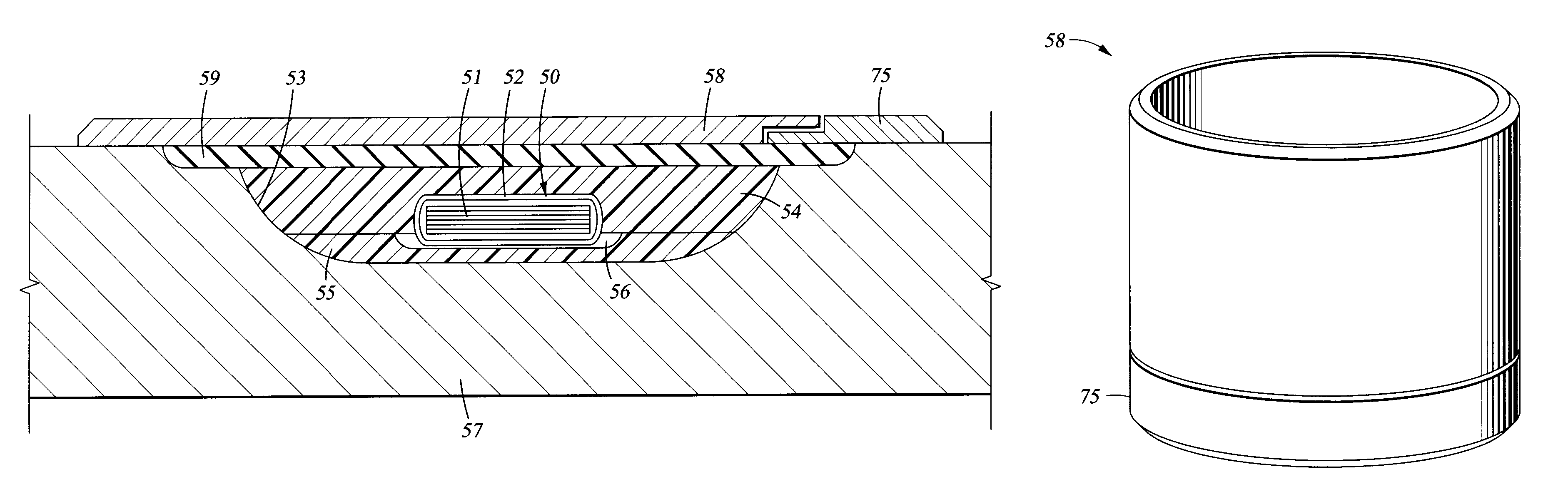
[0044]Embodiments of the present invention relate to methods and apparatus for measuring EM properties of subsurface formations penetrated by a wellbore. Embodiments of the invention include tools capable of determining resistivities in the same region of a formation using both lateral and induction or propagation EM sensors. Some embodiments of the invention relate to methods for the manufacture or assembly of such tools. According to embodiments of the invention, lateral-type and propagation-type sensors are compatibly implemented within a tubular for subsurface use. Combined implementation of the lateral and the propagation sensors on the same tubular makes it possible to use an integrated sensor shield assembly on the tubular, if so desired. More importantly, the implementation of combined lateral and propagation sensors makes it possible to obtain multi-mode resistivity measurements from the same subsurface region in one pass. Thus providing a more accurate and reliable subsurf...


PUM


Abstract

A combined resistivity tool incorporating both induction / propagation antennas and lateral resistivity antennas disposed in recesses of downhole tubulars, in which a lateral resistivity antenna includes an insulating base layer disposed in the recess; a toroidal antenna disposed over the insulating base layer; and a shield disposed over the recess.

Description

BACKGROUND OF INVENTION[0001]1. Field of the Invention[0002]The invention relates generally to the field of subsurface exploration and production. More particularly, the invention relates to methods and apparatus for measuring resistivity properties of earth formations penetrated by a wellbore.[0003]2. Background Art[0004]Resistivity logging tools have been used for many years to measure the resistivities of earth formations surrounding a borehole. Traditionally, resistivity measurements were obtained by lowering a wireline-conveyed logging device into a wellbore after the wellbore was drilled. However, the wireline measurements necessarily involve a delay between the time a well is drilled and when the measurements are acquired. A preferred approach is to make such measurements while the well is being drilled so that corrective steps may be taken if necessary. For example, wellbore information if available in real time may be used to make adjustments to mud weights to prevent forma...

Claims


Application Information

Patent Timeline
28 Apr 2009
Publication
US7525315B2
IPC
G01V3/10; G01V3/18; E21B47/00; E21B47/01; E21B47/12; E21B49/00; G01V3/20; G01V3/26; G01V3/30
CPC
E21B47/01; G01V3/30; E21B47/017; G01V3/26
Inventors
FREDETTE, MARK A.; HALL, JAMES STEPHEN