Disk drive with non-magnetic cover and base plated with conductively connected magnetic shielding layers
a magnetic shielding layer and non-magnetic cover technology, applied in the direction of record information storage, record carrier contruction details, instruments, etc., can solve the problems of increasing the number of parts, affecting the magnetic disk device, and deleting the data recorded on the disk-shaped recording medium
- Summary
- Abstract
- Description
- Claims
- Application Information
AI Technical Summary
Benefits of technology
Problems solved by technology
Method used
Image

Examples
first embodiment
[0017]A first embodiment in which the present invention is applied to an HDD will be described below in detail with reference to the drawings.
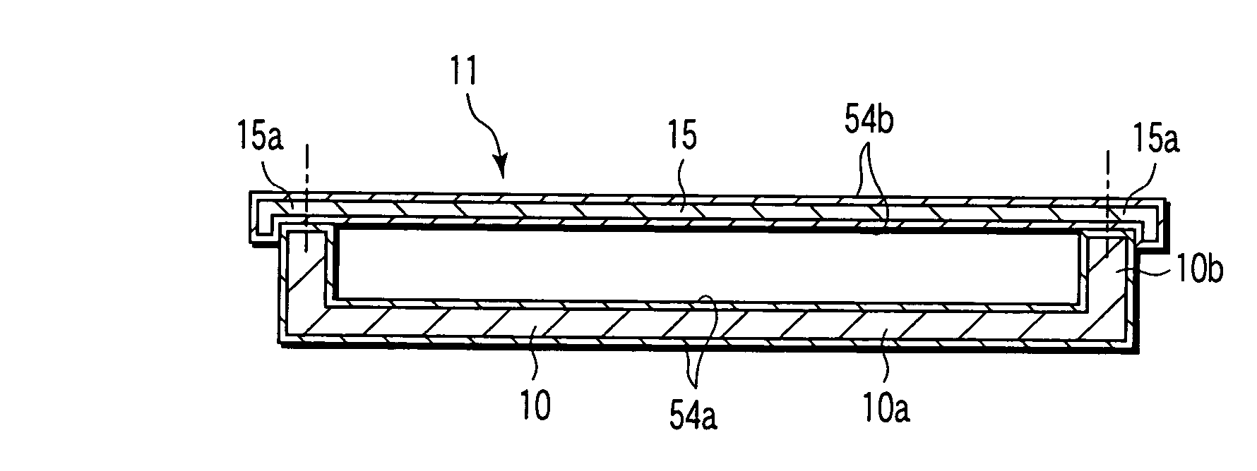
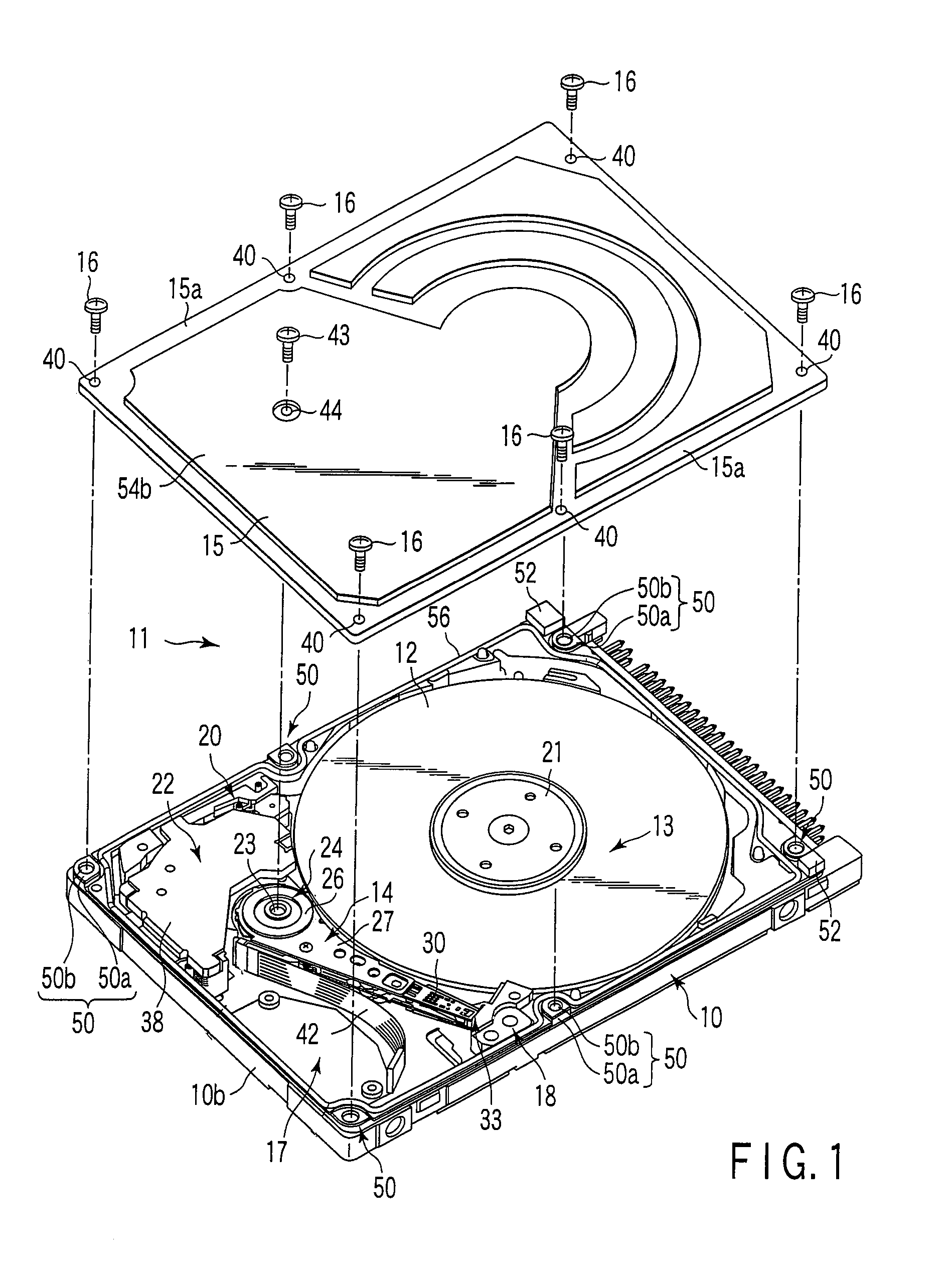
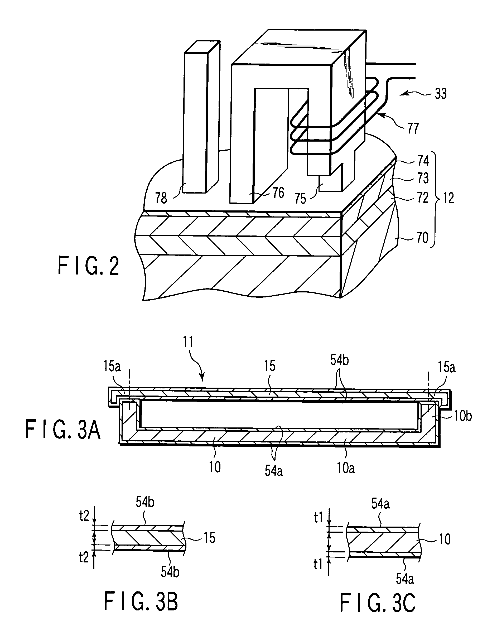
[0018]As shown in FIG. 1, the HDD has a case 11. The case 11 has a rectangular box-shaped base 10 having an open upper surface and a rectangular plate-shaped top cover 15. The top cover 15 is fixed to the base by a plurality of screws and closes the upper opening of the base.
[0019]A magnetic disk 12 as an information recording medium and a mechanical section are disposed in the base 10. The mechanical section includes a spindle motor 13 for supporting and rotating the magnetic disk 12, a plurality of magnetic heads 33 for recording and reproducing information to and from the magnetic disk, a head actuator 14 for movably supporting the magnetic heads 33 with respect to the magnetic disk 12, a voice coil motor (hereinafter, referred to as “VCM”) 22 for rotating and positioning the head actuator, a ramp load mechanism 18 for keeping the magnetic ...
second embodiment
[0038]Next, an HDD according to the present invention will be explained.
[0039]A permeability material, that is, a magnetic material having a larger thickness can more improve a magnetic shield effect. In the first embodiment described above, the plating layers having the uniform thickness t1 or t2 are entirely formed to the outer and inner surfaces of the base 10 and to the outer and inner surfaces of the top cover 15. In this case, although the total thickness of the plating layers formed on the outer and inner surfaces is t1×2 or t2×2, the thickness of the plating layer acting as a path of magnetism is t1 or t2.
[0040]According to the second embodiment, the first and second plating layers are arranged as partly plating layers and formed on a part of the base 10 and a part of the top cover 15 as shown in FIGS. 4A, 4B, and 4C. That is, the first plating layer 54a is formed only on the inner surface of the base 10 to a thickness of 2t1. Here, the inner surface of the base 10 includes ...
third embodiment
[0042]As shown in FIG. 6, the first plating layer 54a is formed only on the outer surface of the base 10 to the thickness of 2t1. The second plating layer 54b is formed only on the outer surface of the top cover 15 to the thickness of 2t2. The first plating layer 54a and the second plating layer 54b are in contact with each other on the outer surface of a side wall 19b and made magnetically conducive with each other.
[0043]The third embodiment can also obtain the same operation / working effect as the second embodiment described above. Note that since the other arrangement of the second and third embodiments is the same as the first embodiment described above, the same portions are denoted by the same reference numerals and the detailed description thereof will be omitted.
PUM
| Property | Measurement | Unit |
|---|---|---|
| thickness | aaaaa | aaaaa |
| thickness | aaaaa | aaaaa |
| thickness | aaaaa | aaaaa |
Abstract
Description
Claims
Application Information
 - R&D
- Intellectual Property
- Life Sciences
- Materials
- Tech Scout
- Unparalleled Data Quality
- Higher Quality Content
- 60% Fewer Hallucinations
Browse by: Latest US Patents, China's latest patents, Technical Efficacy Thesaurus, Application Domain, Technology Topic, Popular Technical Reports.
© 2025 PatSnap. All rights reserved.Legal|Privacy policy|Modern Slavery Act Transparency Statement|Sitemap|About US| Contact US: help@patsnap.com