
Laminated write gap to improve writer performance

a write gap and gap technology, applied in the field of magnetic data storage devices, can solve the problems of reducing the density of data which can be stored on the magnetic disk, affecting the storage of data on adjacent recording tracks of the recording medium, and affecting so as to reduce the interference of adjacent tracks, reduce the write efficiency of the magnetic recording head, and ensure the effect of economic and social benefits

Inactive Publication Date: 2009-04-28
WESTERN DIGITAL TECH INC
View PDF37 Cites 5 Cited by
  • Summary
  • Abstract
  • Description
  • Claims
  • Application Information

AI Technical Summary

Benefits of technology

The patent text describes a way to reduce interference between adjacent tracks in magnetic storage devices without affecting the efficiency of the recording head. This is achieved by using a write gap structure that reduces the generation of magnetic fields in the erase band, resulting in smaller erase bands and closer spacing of recording tracks. This increases data storage density in magnetic disks. The write gap structure includes layers of inert material and magnetic material, with a reduced throat height and a draw of magnetic flux away from regions of the recording head. Overall, this technology allows for reliable and economical fabrication of structures that reduce interference between tracks in magnetic storage devices.

Problems solved by technology

These additional magnetic fields can be problematic because they comprise a weak, unreadable signal which cannot reliably store magnetic charges on the recording medium.
However, they can interfere with the storage of data on adjacent recording tracks of the recording medium by partially overwriting, or even erasing, the data on the adjacent tracks.
However, the extra space required to provide this offset between tracks disadvantageously reduces the density of data which can be stored on the magnetic disk.

Method used


Image

  • Laminated write gap to improve writer performance
  • Laminated write gap to improve writer performance
  • Laminated write gap to improve writer performance

Examples


Embodiment Construction

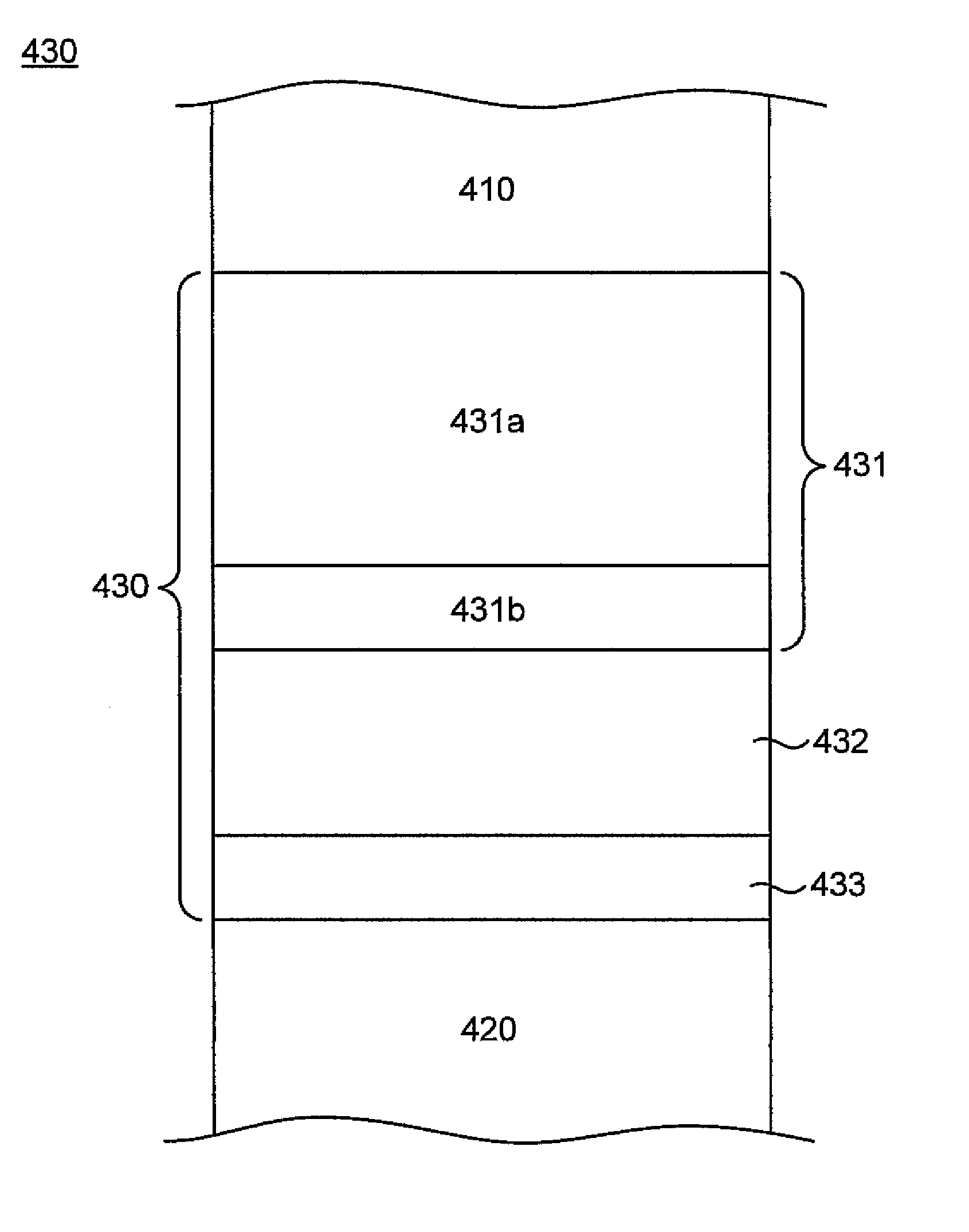
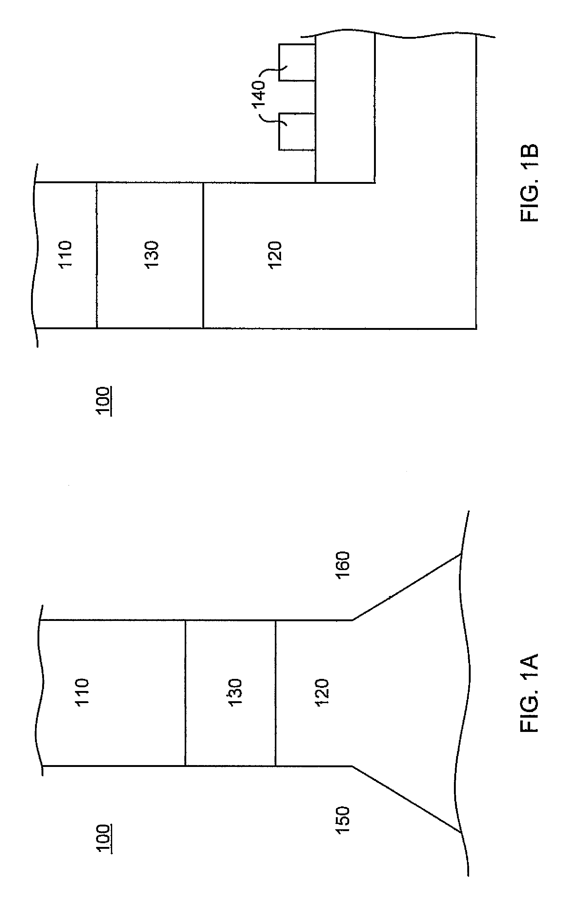
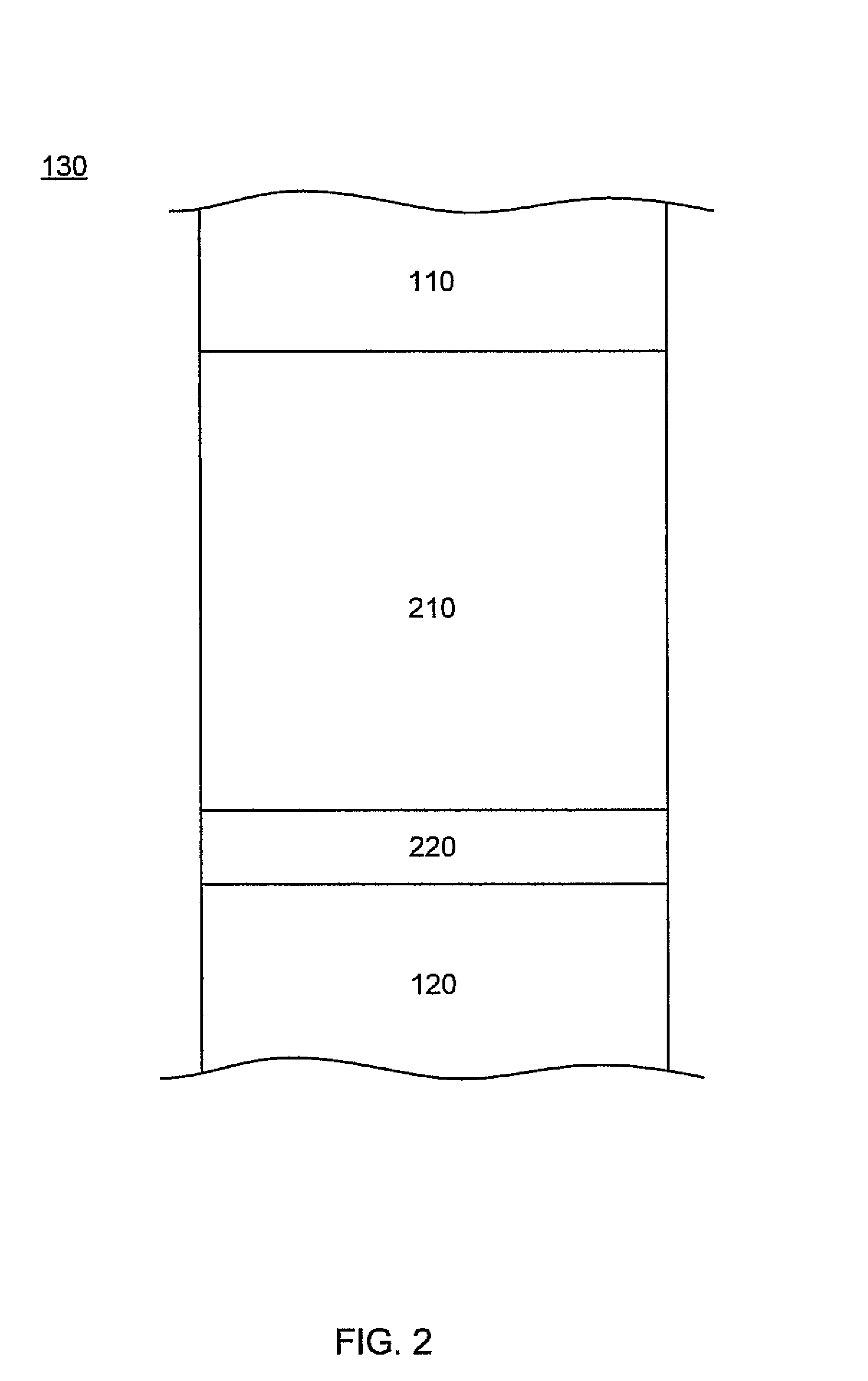
[0022]Reference will now be made in detail to embodiments of the present invention, examples of which are illustrated in the accompanying drawings. While the present invention will be described in conjunction with the following embodiments, it will be understood that they are not intended to limit the present invention to these embodiments alone. On the contrary, the present invention is intended to cover alternatives, modifications, and equivalents which may be included within the spirit and scope of the present invention as defined by the appended claims. Furthermore, in the following detailed description of the present invention, numerous specific details are set forth in order to provide a thorough understanding of the present invention. However, embodiments of the present invention may be practiced without these specific details. In other instances, well-known methods, procedures, components, and circuits have not been described in detail so as not to unnecessarily obscure aspe...


PUM

PropertyMeasurementUnit
thickaaaaaaaaaa
thickaaaaaaaaaa
thickaaaaaaaaaa

Abstract

Embodiments of the present invention recite a write gap structure for a magnetic recording head. In one embodiment, the write gap structure comprises at least one layer of inert material is disposed proximate to the P2 pole of a magnetic recording head. A layer of magnetic material is disposed between the layer of inert material and the P1 pedestal (P1P) of the magnetic recording head. In embodiments of the present invention, the write gap structure further comprises a second layer of inert material is disposed between the layer of magnetic material and the P1P of the magnetic recording head. In embodiments of the present invention, the write gap structure only overlies a portion of the write gap of the magnetic recording head with reference to the throat height dimension of the write gap.

Description

FIELD OF THE INVENTION[0001]Embodiments of the present invention are related to the field of magnetic data storage devices.RELATED APPLICATIONS[0002]This application is related to U.S. patent application, Ser. No. 11 / 104212 by Wen-Chien Hsiao, Terence Lam, Yinshi Liu, Michael Yang, and Samuel Yuan, filed on the same date as the present application, entitled “Process for Fabricating a Magnetic Recording Head with a Laminated Write Gap” with, and assigned to the assignee of the present invention.BACKGROUND OF THE INVENTION[0003]The data storage industry strives for innovations to improve areal density of hard disk drives. Improvements can be achieved through changes to the design of the head, the disk, or a combination of the two (e.g., perpendicular head recording).[0004]FIGS. 1A and 1B show front and side views respectively of an exemplary prior art semiconductor fabricated write head 100 used in a disk storage device. Write head 100 comprises an upper pole 110, also known as a “P2”...

Claims


Application Information

Patent Timeline
Patent Type & Authority Patents(United States)
IPC IPC(8): G11B5/235
CPCG11B5/235G11B5/3116
Inventor HSIAO, WEN-CHIENLAM, TERENCELAMBERTS, BERNDLIU, YINSHIOLSON, TERRYYANG, MICHAELYUAN, SAMUEL
Owner WESTERN DIGITAL TECH INC
Learn More