Extendable electronic immobilization staff

a technology of electronic immobilization and discharge staff, which is applied in the direction of racket sports, clubs, fastening whips, etc., can solve the problems of loosing control, great tragedies, and not having the length to keep unruly individuals

Active Publication Date: 2009-04-28
DOUGLAS STEPHEN C
View PDF5 Cites 17 Cited by
  • Summary
  • Abstract
  • Description
  • Claims
  • Application Information

AI Technical Summary

Benefits of technology

[0017]The invention is advantageous in that it has the unique capability of keeping unruly individuals at a safe distance from police officers, army personnel or security personnel using the device.
[0018]The principal advantage of the extendable electronic discharge staff is its length and extendibility.

Problems solved by technology

Getting too close to the individuals in these situations will cause both the security personnel, and the individual they are endeavoring to subdue, to loose control and cause panic.
Too many times, misunderstandings have led to great tragedies.
Although it has a telescoping feature, it does not have the length to keep unruly individuals at a safe distance, and has only one level of shocking voltage capability.
It also lacks the ruggedness and durability needed in mass volume crowds where multiple contacts / jabs may be required.
The appearance of a gun like device has the potential of further misunderstandings along with the ability of missing the target or hitting the individual in the eye doing permanent damage.
None of the foregoing prior art teaches or suggests the particular unique features of the extendable electronic discharge staff and thus clarifies the need for further improvements in the equipment used by police officers, army personnel or security personnel.

Method used


Image

  • Extendable electronic immobilization staff
  • Extendable electronic immobilization staff
  • Extendable electronic immobilization staff

Examples


Embodiment Construction

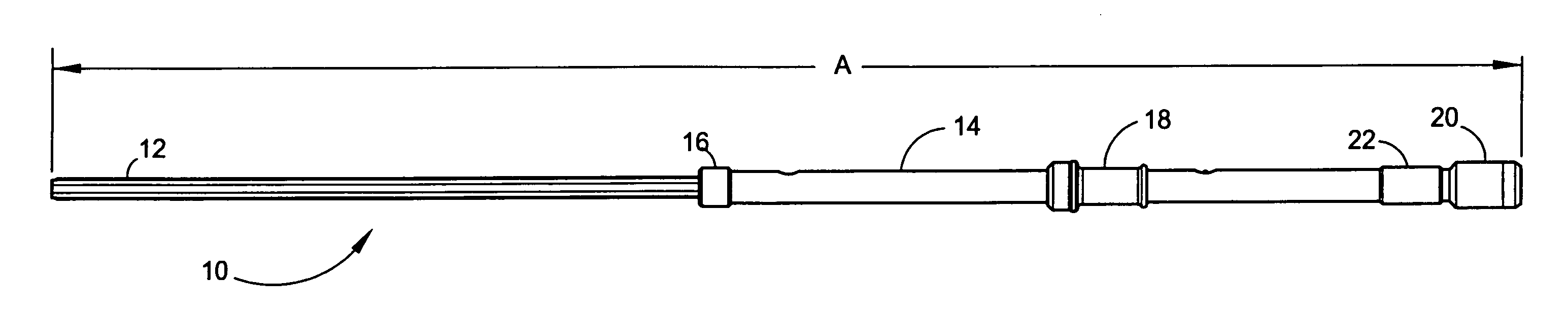
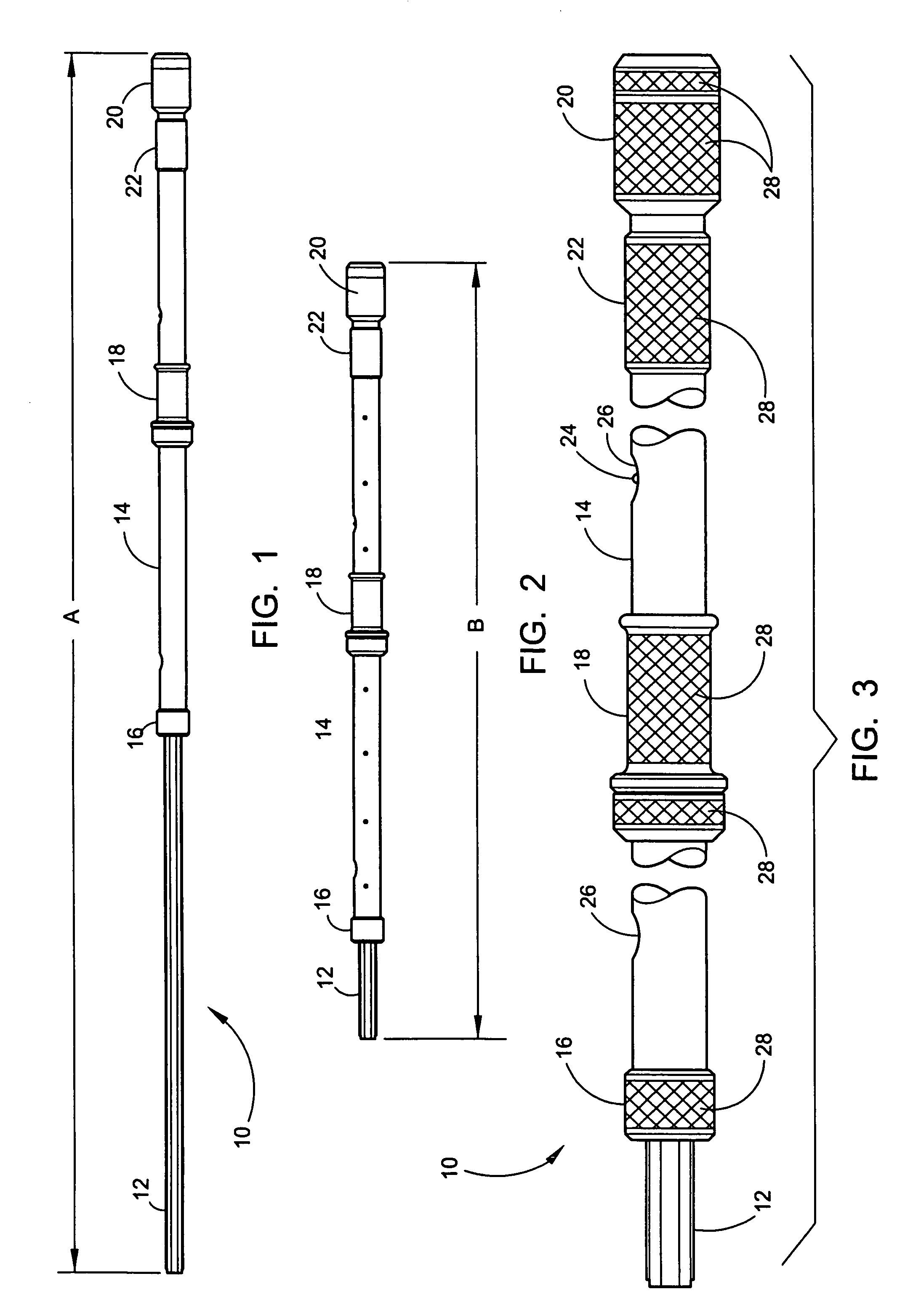
[0050]Referring now to the drawings, wherein similar parts of the extendable electronic discharge staff 10 are identified by like reference numerals, there is seen in FIG. 1 a side view of the extendable electronic discharge staff 10 with the central sliding member assembly 12 in the maximum extended configuration. The tubular body member 14 comprises the body of the device with the position locking mechanism 16 at the forward distal end. An adjustable forward handgrip assembly 18 may be located in various positions along the tubular body member 14 and tightened into position. At the rear of the extendable electronic discharge staff 10 is the electronics compartment 20 adjacent to the spring-loaded rear handgrip assembly 22. In the preferred embodiment, the extendable electronic discharge staff 10 would be a maximum length of seven feet nine inches indicated as the A dimension. It is also anticipated that the average size of the device would be from about 3.5 feet compacted to about...


PUM


Abstract

An extendable electronic discharge staff will consist of a central sliding member translating within a tubular body member to be positioned by the means of a spring-loaded ball detent. When the central sliding member is positioned, it will be locked in place by the means of a locking nut at the distal end of the tubular body member. A forward adjustable handgrip will be located and locked into position along the length of the tubular body member to accommodate the size and comfort of the person using the device. By rotating the rear hand grip, the device will be turned on or off, and by sliding the rear handgrip forward or backward a high or low voltage will be delivered to the distal contact end of the central sliding member. On an alternate embodiment having three contact positions, the default center position delivers low voltage while both forward and backward outer positions deliver high voltage. This action gives the operator two different voltage capabilities along with a visible snapping arc to indicate the potential of the device. A sealed cylindrical housing fixed to the rear of the tubular body member will house a removable battery pack and electronic control module. The device is capable of giving a momentary delivery, a prolonged delivery, or several prolonged deliveries and has been designed not to stun an individual unless necessary, giving the unruly individual several warnings in advance.

Description

FIELD OF THE INVENTION[0001]The present invention relates to an extendable electronic discharge staff used by police officers, army personnel or security personnel to ward off or to stun, through varying degrees of electrical current, individuals in an adverse environment. More specifically, this device keeps a safe, defined distance between the operator and the individual, clearly emphasizing the consequences if contact is made with the device. This device has been designed not to stun an individual unless necessary, giving the unruly individual several warnings in advance. The first warning would be verbal, explaining at a distance the potential dangers. Second would be the snapping arc at the distal end of the device. The third would be a low voltage shock delivered to the individual. If all else fails, the device is capable of delivering a high voltage stunning shock that will incapacitate most people for a short period of time. The device is capable of giving a momentary delive...

Claims


Application Information

Patent Timeline
Patent Type & Authority Patents(United States)
IPC IPC(8): F41B15/04
CPCF41B15/027F41B15/04F41H13/0018
Inventor DOUGLAS, STEPHEN C.
Owner DOUGLAS STEPHEN C
Why Eureka
Try Eureka