

Integrated reading light and personal air outlet
a reading light and integrated technology, applied in the field of aircraft passenger service units, can solve the problems of affecting the aesthetics of the overhead system, requiring more space to provide the necessary functions of the psu system, and increasing weight and cos
- Summary
- Abstract
- Description
- Claims
- Application Information
AI Technical Summary
Benefits of technology
Problems solved by technology
Method used
Image

Examples
Embodiment Construction
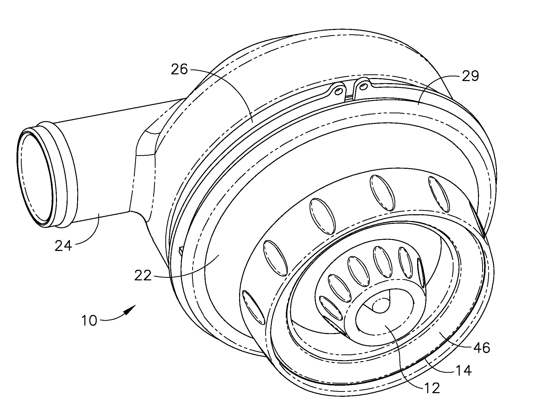
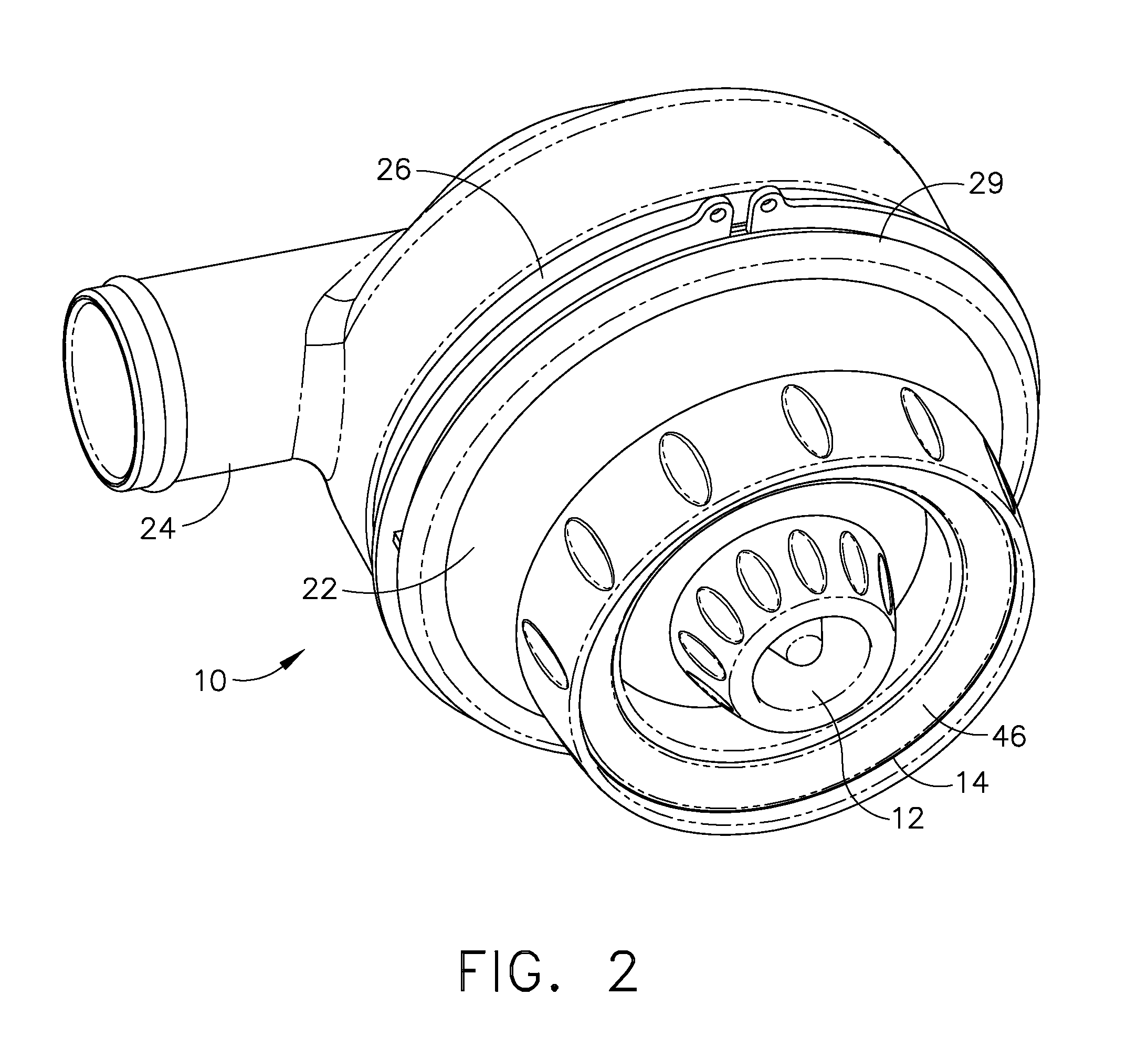
[0014]As shown in FIGS. 2 and 4, the present invention provides an integrated light and air assembly 10 for an aircraft PSU which employs a personal air outlet (PAO) 12 concentrically surrounded by a light ring 14 employing multiple individual light emitting diodes (LEDs) 16 as light sources for the embodiment shown. The PAO incorporates a partial spherical body 18 which, for the embodiment shown in the drawings, is carried in an inner race 19 providing a front hemispherical engagement having an outer element 20 suspended by a partial spherical surface 21 in a housing 22 of the integrated assembly. A snap ring 23 secures the outer element of the inner race to the housing and a threaded insert 25 provides a rear hemispherical engagement to secure the body in the inner race. A connector 24 extends from the housing for attachment to a duct in the low pressure low volume air system contained within the PSU fascia or cabin ceiling of the aircraft. The housing also employs a substantially...
PUM
 Abstract
Description
Claims
Application Information