Fiber optic devices having volume Bragg grating elements

a fiber optic device and volume bragging technology, applied in the field of fiber optic devices, can solve the problems of limited use of filters, inability to recognize wavelengths of light with the intention of achieving practical device functionality, and inability to record such filters

Active Publication Date: 2009-05-05
NECSEL INTPROP
View PDF84 Cites 98 Cited by
  • Summary
  • Abstract
  • Description
  • Claims
  • Application Information

AI Technical Summary

Problems solved by technology

However, to the inventors' knowledge, even though the wavelength selectivity of the volume Bragg gratings was the underlying mechanism that enabled white-light reconstruction of thick-layer DCG display holograms, their utility for separating, combining, or otherwise manipulating specific wavelengths of light with the intention of achieving practical device functionality has not been recognized.
A principal issue, however, is that recording of such filters must be performed at the same wavelength at which the filter will subsequently operate.
As a result, the use of these filters is limited to a very limited range of wavelengths where sufficiently powerful lasers exist.
Furthermore, the list of appropriate recording materials is confined to two or three narrow classes of photorefractive materials, which often have physical properties that are unsuitable for their intended mode of operation.
Nonetheless, this approach is still rather limited due to a number of factors.
This factor substantially limits the usefulness of this type of filter.
This approach also requires the use of at least two (and typically four) polished surfaces that are orthogonal to each other, which increases the complexity of the filter manufacturing process and its cost.
As a result, the wavelength must be controlled precisely for any practical device and is, therefore, unique for a particular wavelength or information-carrying “channel” of light, which complicates the issues in manufacturing of these elements.

Method used


Image

  • Fiber optic devices having volume Bragg grating elements
  • Fiber optic devices having volume Bragg grating elements
  • Fiber optic devices having volume Bragg grating elements

Examples


Embodiment Construction

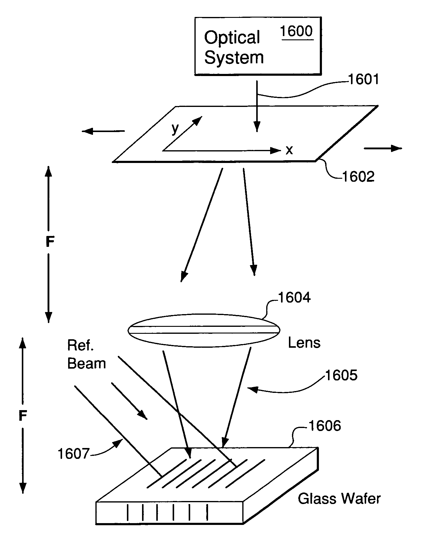
[0032]Using Sensitized Silica Glasses for Manufacturing of VBG Filters

[0033]One of the major problems in developing and using any kind of permanent VBG filters for practical applications has been the unavailability of a material or a class of materials possessing physical properties that are adequate for the practical applications. For example, the photorefractive electro-optic crystals, in which much of the research was conducted on the subject of VBGs, among other problems, are incapable of providing truly permanent, stable recording across a wide temperature range. Furthermore, these crystals are strongly anisotropic, which limits their usage substantially. For these reasons, an entire range of applications of VBG filters in general has not been substantially explored. In fact, to the inventors' knowledge, there is not a single photonic device now in the market that uses VBG elements.

[0034]According to the invention, a previously unexplored class of materials, the silicate photor...


PUM


Abstract

Apparatus and methods for controlling the spectral shape of a Bragg grating element (“VBG”) filter are disclosed. An optical system can be adapted to deliver a recording beam to the front focal plane of a lens. The recording beam may cause to be formed, in the front focal plane of the lens, an optical distribution that represents the desired filter response of the VBG element. A recording medium sample may be placed in the back focal plane of the same lens. The lens creates a true Fourier transform of the distribution in the optical plane directly on the recording medium. Via coherent interference with the plane reference wave, both the amplitude and the phase of the Fourier transform are transferred to the amplitude and phase envelope of the VBG imprinted on the recording material. A mask representing the desired filter shape may be placed in the front focal plane of the lens. The recording beam may be shone through the mask, such that a masked recording beam exits the mask in the front focal plane of the lens. The masked recording beam may represent the desired filter response of the VBG element.

Description

CROSS-REFERENCE TO RELATED APPLICATIONS[0001]This application is a continuation-in-part of U.S. patent application Ser. No. 11 / 173,914, filed Jul. 1, 2005, which is a division of U.S. patent application Ser. No. 10 / 390,521, filed Mar. 17, 2003, which claims benefit under 35 U.S.C. § 119(e) of provisional U.S. patent application No. 60 / 365,032, filed Mar. 15, 2002, the disclosure of which is hereby incorporated herein by reference.FIELD OF THE INVENTION[0002]The invention is related generally to fiber optic devices. More generally, the invention relates to fiber optic devices having one or more volume Bragg grating (VBG) elements, and methods for making such VBG elements.BACKGROUND OF THE INVENTION[0003]Light wavelength selectivity of thick periodic structures was, historically, studied first in x-ray diffraction on crystalline solids. It was recognized that such selectivity arises due to the coherent addition of the light energy diffracted by individual layers forming precisely spac...

Claims


Application Information

Patent Timeline
Patent Type & Authority Patents(United States)
IPC IPC(8): G02B6/34G02B5/32
CPCG02B5/203G02B6/2931G02B6/29311G02B6/29383G02B6/4215G02B6/4246G03H1/0005G03H1/0248G03H1/16
Inventor VOLODIN, BORIS L.BAN, VLADIMIR SINISA
Owner NECSEL INTPROP
Why Eureka
Try Eureka