
Keyboard or other input device using ranging for detection of control piece movement

a control piece and range detection technology, applied in the field of keyboards and other computer input devices, can solve the problems of not being able to operate in strong ambient lighting conditions, not being able to completely substitute mechanical keyboards, and conventional keyboard technology limiting the degree to which keyboard manufacturing costs can be reduced

Inactive Publication Date: 2009-05-05
MICROSOFT TECH LICENSING LLC
View PDF84 Cites 87 Cited by
  • Summary
  • Abstract
  • Description
  • Claims
  • Application Information

AI Technical Summary

Benefits of technology

Enables cost-effective, tactile, and flexible key detection independent of ambient lighting and surface, with improved manufacturing flexibility and user interaction.

Problems solved by technology

Although useful, such technology is not a complete substitute for a mechanical keyboard.
For example, many users rely on the tactile sensation of pressing keys; virtual keyboards do not offer this feature.
Moreover, projected keyboards require a flat surface in order to function, and may not operate well in strong ambient lighting conditions.
Conventional keyboard technology limits the degree to which keyboard manufacturing costs can be reduced.

Method used


Image

  • Keyboard or other input device using ranging for detection of control piece movement
  • Keyboard or other input device using ranging for detection of control piece movement
  • Keyboard or other input device using ranging for detection of control piece movement

Examples


Embodiment Construction

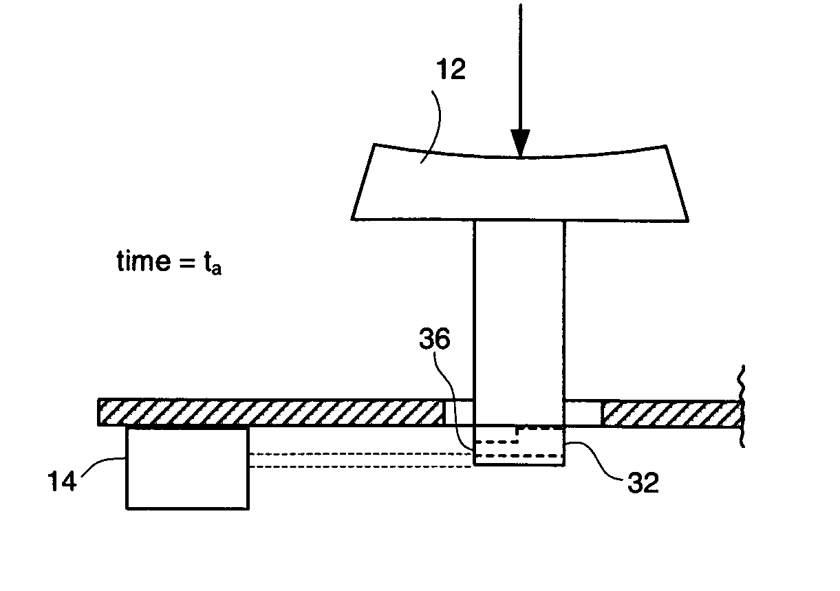
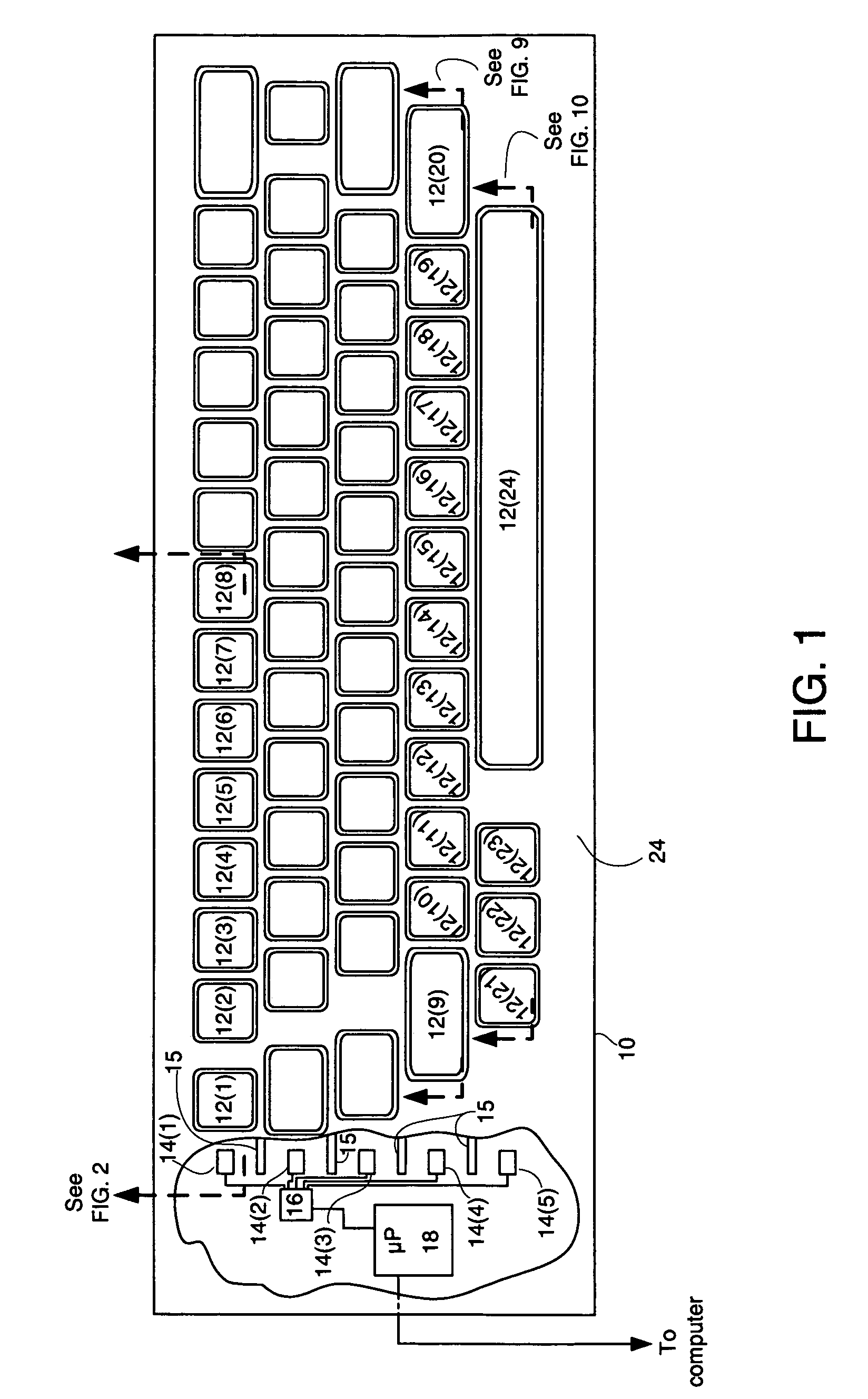
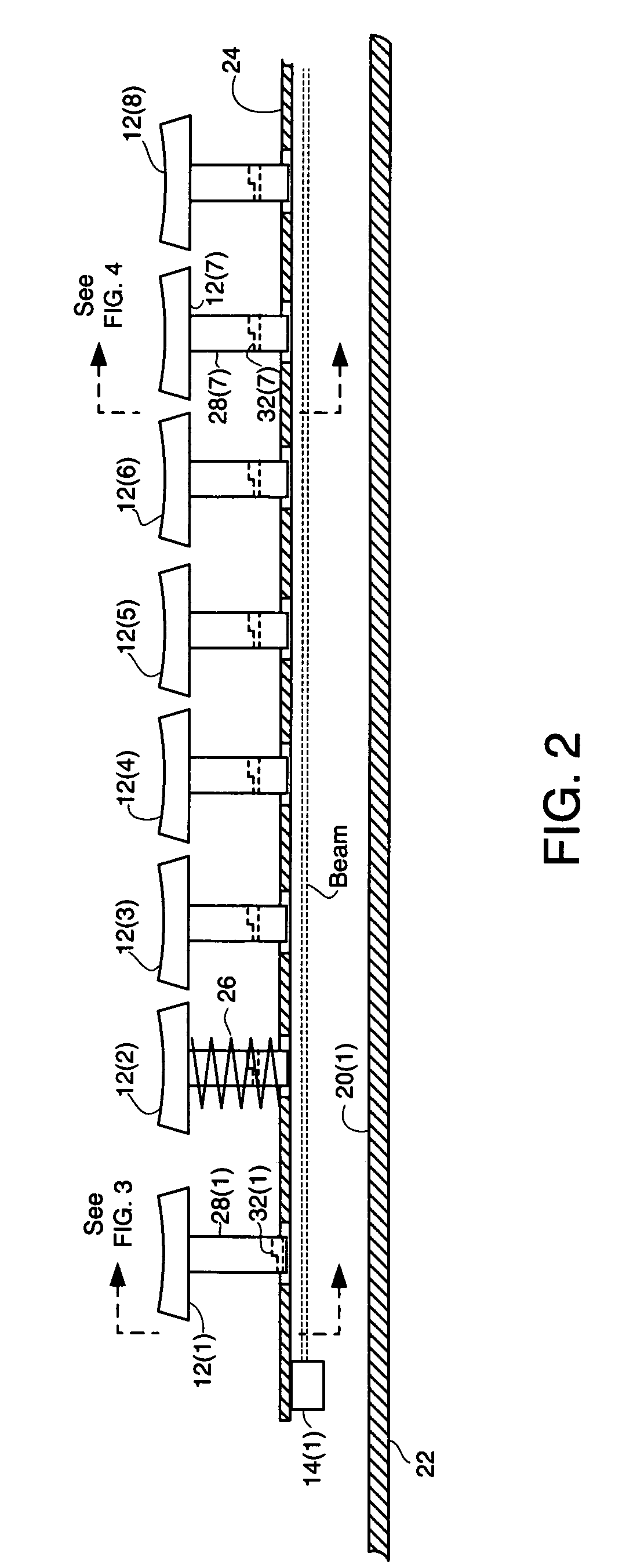
[0031]FIG. 1 is a diagram of a keyboard 10 according to at least some embodiments of the invention. Although keyboard 10 is shown with a collection of keys arrayed in a manner similar to that of a common office keyboard, the invention is not limited by the type, number or arrangement of keys or other user controls. For ease of reference, but so as to avoid unnecessary detail, a portion of the keys shown in FIG. 1 are numbered 12(1)-12(24). The keys of keyboard 10 are attached to portions (not shown in FIG. 1 but shown in FIG. 2) extending through an upper case 24. Shown in a partial cutaway at the side of keyboard 10 are five laser range detection sensors 14(1)-14(5) positioned at the far end of each row of keys. Separating each key row is a baffle 15. Baffle 15 prevents light reflected from a key in one row from reaching a sensor corresponding to another row. Each of sensors 14(1)-14(5) includes a laser diode and associated range sensing module.

[0032]Each of sensors 14(1)-14(5) is ...


PUM


Abstract

A keyboard detects press or release of keys using one or more ranging techniques. Targets are attached to keys of the keyboard. As keys are pressed or released, attached targets move into paths of distance measuring sensors. A range finder determines sensor-target distances and reports those distances to a microprocessor. Based on that distance data, the microprocessor identifies the moved keys. The keys and microprocessor are configured to determine the direction of key motion and to detect simultaneous press or release of keys in a single row or column. A slider control, and / or an integral pointing device tracking motion of a user's finger or other object, may also be included.

Description

FIELD OF THE INVENTION[0001]This invention relates to computer input devices. In particular, this invention relates to keyboards and other computer input devices and manners in which actuation of a key or other user control component may be detected.BACKGROUND OF THE INVENTION[0002]The keyboard is an import tool for providing textual, command and other input to a computer or other electronic device. Although pointing devices (e.g., mice, touchpads, etc.), handwriting detectors (e.g., electronic digitizers and styli) and other input mechanisms continue to develop and offer numerous advantages in many situations, the keyboard will remain a primary input device for the foreseeable future. As critical as keyboards are, however, the basic design has remained the same for many years. In particular, a keyboard generally includes a matrix of electrical switches resting beneath a collection of keys. When a key is pressed, an electrical contact is made in the corresponding switch. A microproc...

Claims


Application Information

Patent Timeline
Patent Type & Authority Patents(United States)
IPC IPC(8): G06F3/02
CPCG06F3/0202G06F3/0213H03M11/26
Inventor KONG, YUAN
Owner MICROSOFT TECH LICENSING LLC
Learn More