Method for stabilizing the size of a focal spot of an X-ray tube, and X-ray tube comprising such a method

a technology of x-ray tubes and focal spots, which is applied in the direction of electric discharge tubes, instruments, basic electric elements, etc., can solve the problems of limiting the resolution of a radiography image obtained from the focal spot, affecting the quality of the images produced, and the drawbacks of x-ray tubes

Active Publication Date: 2009-05-05
GENERAL ELECTRIC CO
View PDF10 Cites 4 Cited by
  • Summary
  • Abstract
  • Description
  • Claims
  • Application Information

AI Technical Summary

Benefits of technology

[0018]Embodiments of the invention overcome one or more of the drawbacks of the techniques explained above. To this end, embodiments of the invention proposes to modify the techniques of biasing the existing concentrator in order to control, compensate for and standardise firstly the size of the focal spot and, secondly, the contrast modulation function. Embodiments of the present invention thus enable instantaneous, high-precision checking and regulation of the size of the focal spot and the of contrast modulation function.
[0021]Embodiments of the invention can also be used for the analysis, for each applied bias voltage, of the thermal load of the focal spot on the anode and the heating current of the filament in order to measure the rate of impact that they exert on the tube in operating mode. This rate of impact is linked to the service life of the tube and its capacity to carry out a cycle of exposures. To optimise the operation of the tube, an embodiment of the invention provides for the inclusion of these measurements of the rate of impact in the production of the bias voltage in order to obtain a compromise between the stability of the contrast modulation function, the size of the focal spot and the tolerated impact rate. This analysis therefore enables embodiments of the invention to adjust the level of the desired contrast modulation function and the optimum size of the focal spot in taking account of the measurements of rate of impact, thus enabling the service life of the X-ray tube to be increased. To do this, an embodiment of the invention defines a range of operation of the tube in which this compromise is implemented.
[0023]Embodiments of the present invention therefore relate to a fixed-anode or rotating-anode X-ray tube used to obtain radiology images, in which the sharpness and contrast are considerably improved and maintained.

Problems solved by technology

However, these X-ray tubes have drawbacks.
The variation of the contrast modulation function may impair the quality of the images produced.
This impairment may thus limit the resolution of a radiography image obtained from the focal spot, making it more difficult to detect small-sized microcalcifications for example, in the case of mammography.
The bias voltage is therefore no longer efficient when the power supply voltage and / or the electron current of the tube vary, giving rise to a variation in the size of the focal spot and, potentially, a reduction of the sharpness and contrast of the radiography image.
When there is a variation in the power supply voltage and the electron current of the tube, the associated variation in the size of the focal spot may lead to excessive energy being obtained.
This excessive energy may damage the surface of said focal spot.

Method used


Image

  • Method for stabilizing the size of a focal spot of an X-ray tube, and X-ray tube comprising such a method
  • Method for stabilizing the size of a focal spot of an X-ray tube, and X-ray tube comprising such a method
  • Method for stabilizing the size of a focal spot of an X-ray tube, and X-ray tube comprising such a method

Examples


Embodiment Construction

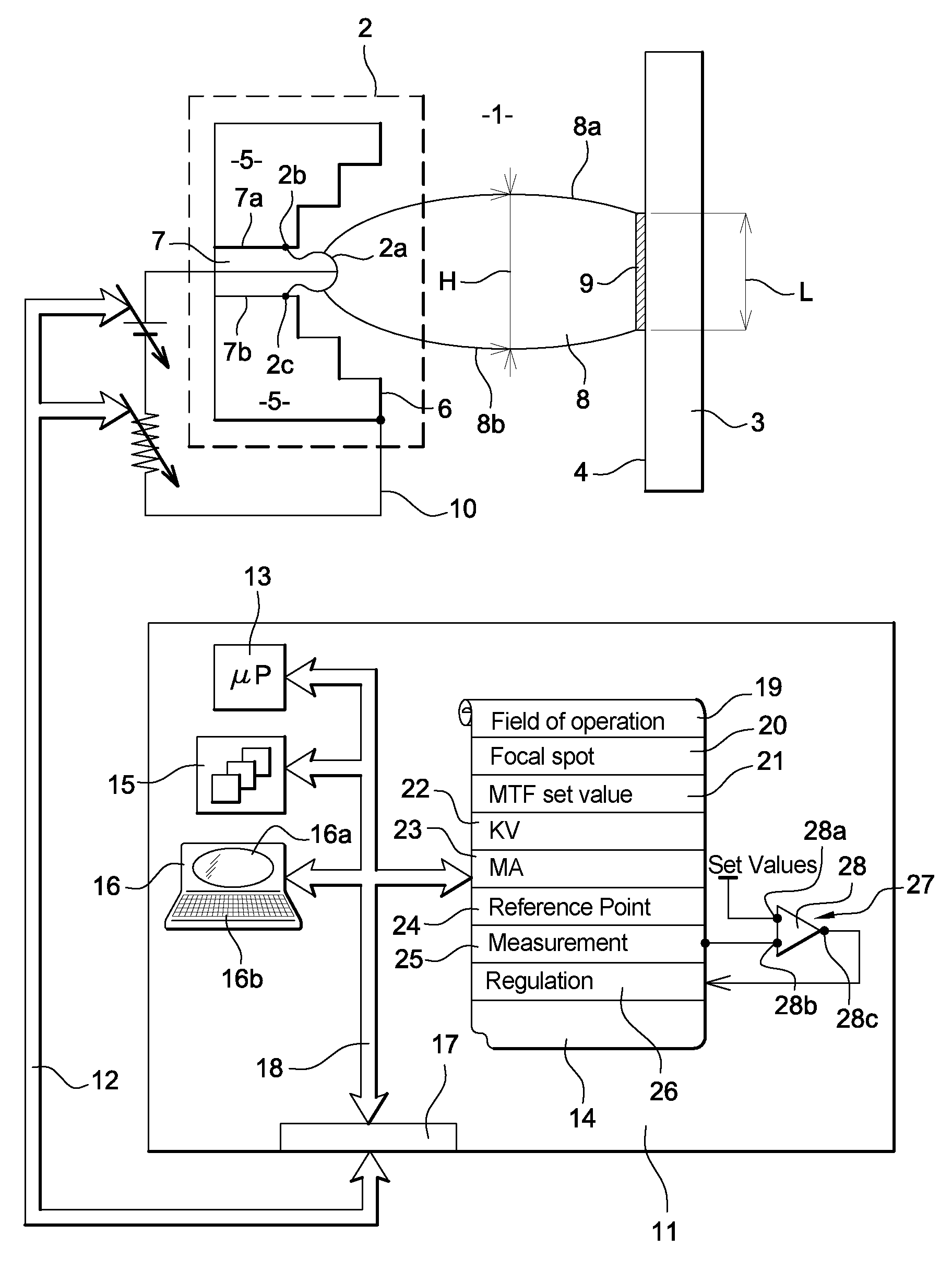
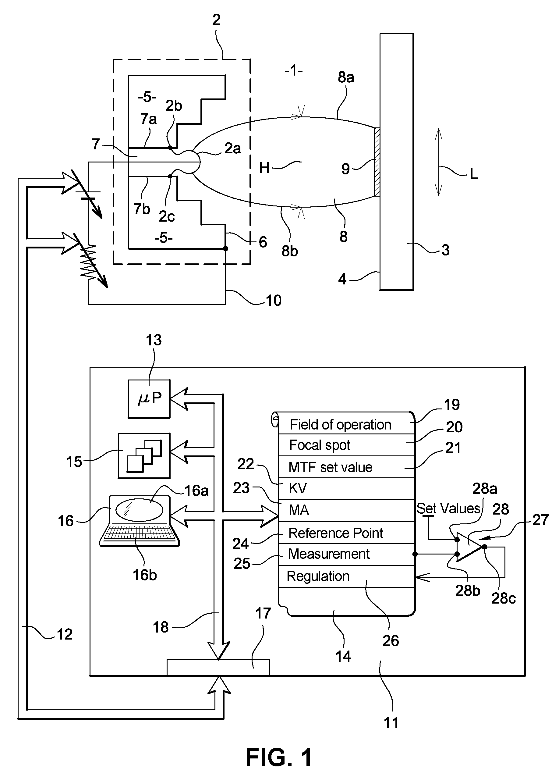
[0049]FIG. 1 is a schematic view of the structure of an X-ray tube 1 configured according to an embodiment of the invention. The tube 1 has a cathode 2 and an anode 3, for example of a rotating type. The cathode 2 is either a direct cathode or an indirect cathode. The cathode 2 and the anode 3 are placed so as to be facing each other. They are both contained in a conventional way in a glass or metal envelope (not shown).

[0050]The anode 3 is constituted, at least partially, by an X-ray emitting material forming a massive structure with one surface that constitutes a plane face 4 of the anode 3 oriented towards the cathode 2.

[0051]The term “X-ray emitting material” is understood to mean a refractory material that is a good conductor of heat and has a highly atomic number of the kind commonly used to obtain X-rays under electron bombardment, for example a material such as tungsten, molybdenum, rhenium, rhodium, their alloys etc. Such materials are called target material here below in t...


PUM


Abstract

In a method for stabilizing the size of a focal spot of an X-ray tube and contrast modulation function of a X-ray tube, the tube has a cathode comprising a concentrator and a heating filament. It has an anode is placed so as to be facing the cathode. With the filament, the cathode produces an electron beam bombarding the focal spot of the anode. A bias voltage is applied between a terminal of the filament and a terminal of the concentrator. The tube has means to measure the size of the focal spot and the function of contrast modulation. It also has means to regulate the size of the focal spot and the contrast modulation function by means of a bias voltage.

Description

BACKGROUND[0001]1. Field of the Invention[0002]Embodiments of the invention provide a method for standardising the size of a focal spot of an X-ray tube, and find particularly advantageous but non-exclusive application in the field of medical imaging. However, embodiments of the invention can also be applied to other fields in which radiography or radiology examinations are made.[0003]Embodiments of the invention are configured to control, optimise and standardise the size of the focal spot of an X-ray tube.[0004]Embodiments of the invention may standardise a contrast modulation function in an image produced.[0005]Embodiments of the invention may also keep the quality of the images produced constant in all the fields of operation of the X-ray tube.[0006]Embodiments of the invention may also increase the service life or operating life of an X-ray tube.[0007]Embodiments of the invention also relate to X-ray tubes configured to operate using a method described herein.[0008]2. Descripti...

Claims


Application Information

Patent Timeline
Patent Type & Authority Patents(United States)
IPC IPC(8): H01J35/14
CPCH01J35/14H05G1/26H05G1/52H01J35/147
Inventor GAUDIN, CHRISTELLEBLIN, PHILIPPE
Owner GENERAL ELECTRIC CO
Why Eureka
Try Eureka