Method and apparatus for processing printed sheets incorporated reference

a technology for processing printed sheets and apparatuses, applied in the direction of printing, thin material processing, article delivery, etc., can solve the problems of large size of complicated structure, and disadvantageous plurality of conveying paths of conventional printed sheet processing apparatus, so as to reduce the size of the apparatus

Active Publication Date: 2009-05-12
TOSHIBA TEC KK
View PDF14 Cites 23 Cited by
  • Summary
  • Abstract
  • Description
  • Claims
  • Application Information

AI Technical Summary

Benefits of technology

[0010]An object of the present invention is to provide a method and apparatus for processing printed sheets which use a shorter conveying path to reduce the size of the apparatus.
[0017]According to the present invention, the standby tray enables a shorter sheet conveying path to be configured to reduce the size of the apparatus. The assist arm further inhibits the sheets on the standby tray from being warped or deformed. This allows the sheets to be appropriately placed on the standby tray. The sheets can maintain a stable posture when dropped from the standby tray onto the processing tray.

Problems solved by technology

This conventional printed sheet processing apparatus disadvantageously has the longer conveying path and is thus large.
Further, the conventional printed sheet processing apparatus disadvantageously has the plurality of conveying paths and thus a complicated structure.
However, depending on sheet type (sheet size or thickness) or print pattern, the sheets on the standby tray may be deformed, for example, warped or curled, and may thus be inappropriately placed on the standby tray.
Accordingly, it is sometimes difficult to stably drop the sheets simply by opening the tray member and using the paddle to strike the sheets.

Method used


Image

  • Method and apparatus for processing printed sheets incorporated reference
  • Method and apparatus for processing printed sheets incorporated reference
  • Method and apparatus for processing printed sheets incorporated reference

Examples


first embodiment

[0042]the present invention will be described below in detail with reference to FIGS. 1 to 10.

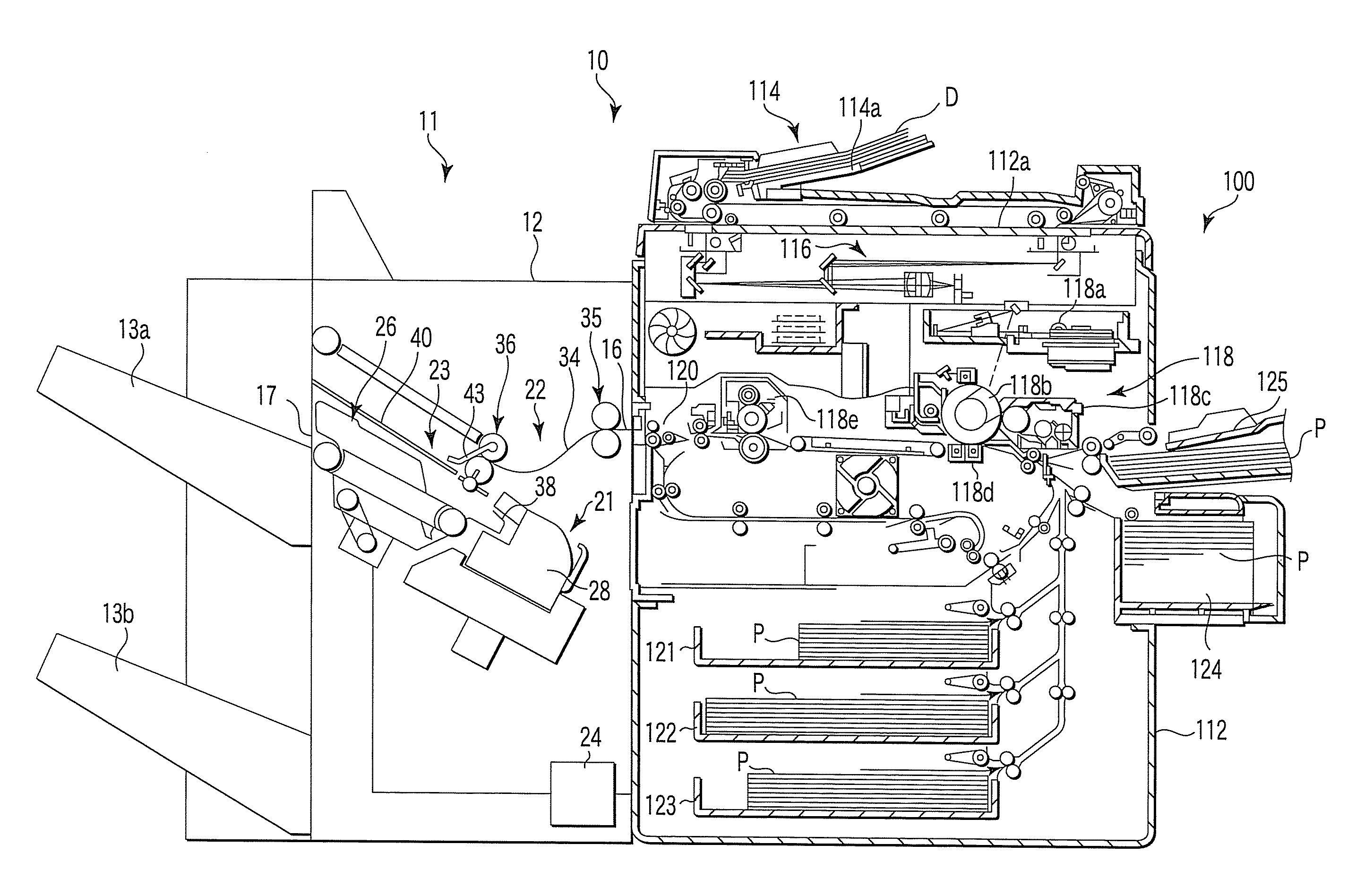
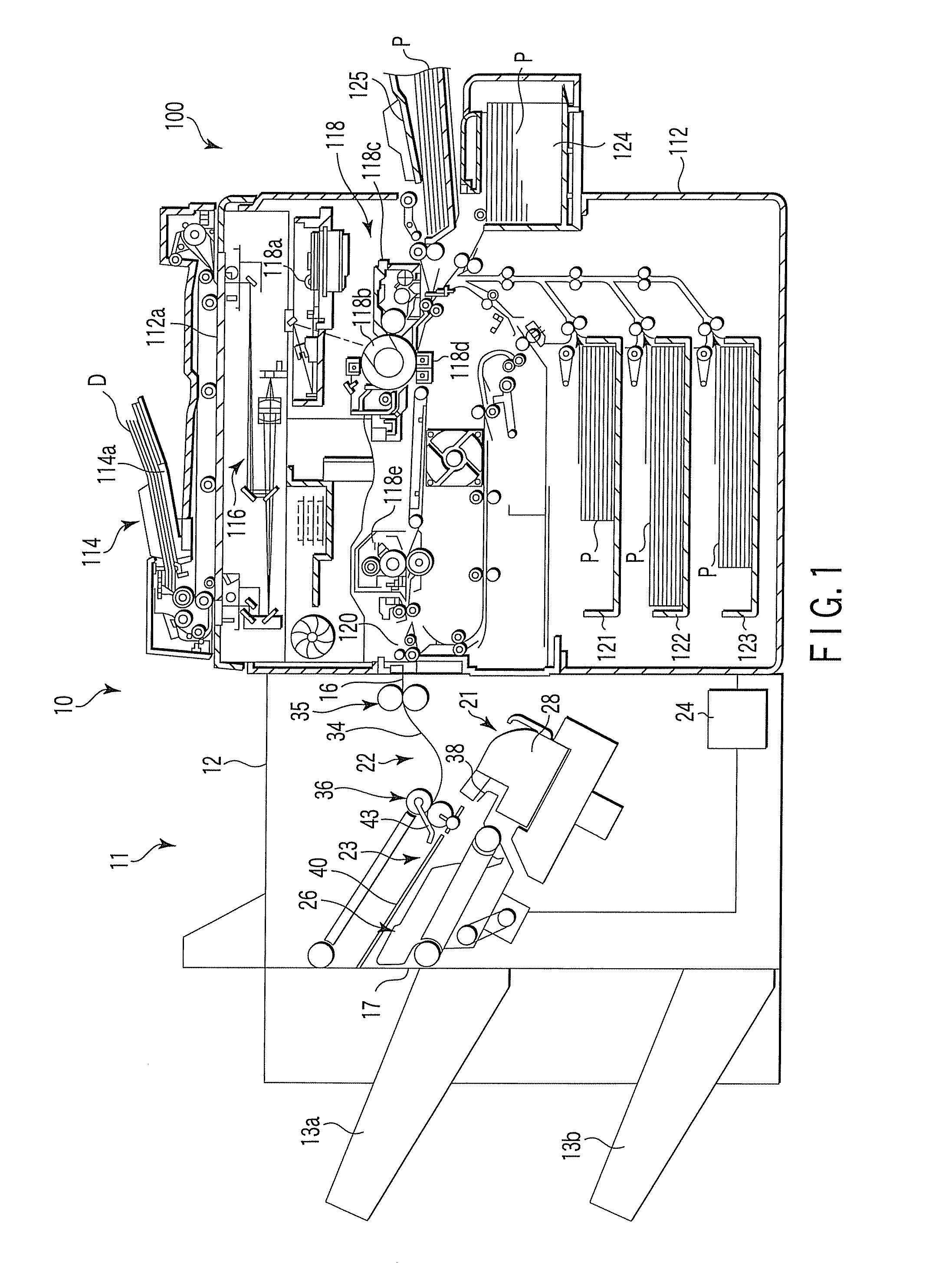
[0043]FIG. 1 shows a schematic diagram of a multi-function peripheral (hereinafter simply referred to as an MFP) 10. The MFP consists of a printed sheet processing apparatus 11 according to an embodiment of the present invention and a digital copier 100 to which the printed sheet processing apparatus 11 is connected. The digital copier 100 is an example of an image forming apparatus according to the present invention.

[0044]The digital copier 100 has a housing 112 constituting a jacket of the apparatus and a original receiving glass 112a consisting of a transparent glass plate, on a top surface of the housing 112. An automatic original feeder 114 (hereinafter simply referred to as an ADF 114) is provided on the original receiving glass 112a so that it can be opened and closed. The ADF 114 automatically feeds a original D to a predetermined position on the original receiving glass 112a.

[0045...

second embodiment

[0102]With reference to FIGS. 15 to 21, description will be given of operation of the printed sheet processing apparatus 11 configured as described above.

[0103]FIG. 15 shows that the first sheet P sits on the standby tray 40, while the second sheet P is being supplied to the standby tray 40. The second sheet P moves on the conveying path 34 toward the outlet roller pair 36, while actuating the sensor 37, located in the middle of the conveying path 34. The assist arm 43 is in its elevated position to guide the sheet P to the standby tray 40. On this occasion, the tray members 45 of the standby tray 40 are in the first (closed) position to allow sheets P to be placed on the standby tray 40.

[0104]As shown in FIG. 12, the lateral pair of tray members 45 supports the opposite ends of a sheet P in its width direction. The sheet receiving member 57 of the paddle mechanism 42 supports the vicinity of widthwise center of rear end of the sheet P. As shown in FIG. 15, a predetermined number o...

third embodiment

[0120]The arm driving mechanism 91 of printed sheet processing apparatus 11 of the third embodiment also acts as a driving source for the roller member 44. The roller member 44 has a discharging function for discharging sheets that are not formed into a pile of sheets, from the standby tray 40 to the outside of the apparatus 11. The arm driving mechanism 91 comprises a stepping motor 93, a cam 94, a first belt member 95, and a second belt member 96. The first belt member 95 transmits the driving force of the stepping motor 93 to the roller member 44. The second belt member 96 transmits the driving force transmitted to the roller member 44, to the cam 94.

[0121]The roller member 44 contains a one-way clutch 92. Rotating the stepping motor 93 in the first direction rotates the first belt member 95, which in turn rotates the roller member 44 in the direction in which a sheet P is fed. In this case, the one-way clutch 92 is actuated and the second belt member 96 remains stopped. Thus, ro...


PUM

PropertyMeasurementUnit
weightaaaaaaaaaa
widthaaaaaaaaaa
weightaaaaaaaaaa

Abstract

An apparatus for processing printed sheets includes a processing tray and a standby tray having a pair of tray members that are movable in a width direction of sheets. The tray members are movable between a first position where a sheet is placed on the tray members and a second position where the sheet is dropped from the tray members. A roller mechanism for feeding the sheet onto the standby tray, a paddle mechanism, and an assist arm are arranged near a rear end of the standby tray. As the tray member moves from the first position to the second position, the paddle mechanism strikes a rear end of the sheet downward. The assist arm is placed near the roller mechanism to inhibit the rear end of the sheet from floating from the standby tray while the tray member is moving from the first position to the second position.

Description

CROSS-REFERENCE TO RELATED APPLICATIONS[0001]This application is based upon and claims the benefit of priority from prior Japanese Patent Applications No. 2005-268881, filed Sep. 15, 2005; and No. 2005-270512, filed Sep. 16, 2005, the entire contents of both of which are incorporated herein by reference.BACKGROUND OF THE INVENTION[0002]1. Field of the Invention[0003]The present invention relates to an apparatus for processing printed sheets, for example, a finisher, which is connected to an image forming apparatus, as well as a method for processing printed sheets.[0004]2. Description of the Related Art[0005]A printed sheet processing apparatus such as a finisher is known which staples a pile of sheets (for example, copy sheets) printed by an image forming apparatus such as a digital copier. This printed sheet processing apparatus comprises a first sheet conveying path, a second sheet conveying path, and a processing tray on which sheets are stapled. The second sheet conveying path ...

Claims


Application Information

Patent Timeline
Patent Type & Authority Patents(United States)
IPC IPC(8): B65H31/00
CPCB42C1/12B65H29/34B65H31/26B65H31/3018B65H2301/422615B65H2404/63
Inventor TERAO, YASUNOBUYAMAMOTO, MIKIOIIJIMA, TOMOMIKAWAGUCHI, TAKAHIROTAKI, HIROYUKI
Owner TOSHIBA TEC KK
Why Eureka
Try Eureka