Virtual load monitoring system and method

a load monitoring and virtual load technology, applied in the direction of testing/monitoring control systems, program control, instruments, etc., can solve the problems of parts that require service or replacement earlier than planned or parts that fail, designers tend to be conservative and over-design parts having properties, etc., to achieve the effect of convenient or more efficient obtaining

Active Publication Date: 2009-05-12
SIKORSKY AIRCRAFT CORP
View PDF9 Cites 14 Cited by
  • Summary
  • Abstract
  • Description
  • Claims
  • Application Information

AI Technical Summary

Benefits of technology

[0010]During the actual signal estimation process during part operation, state parameters measured during part operation are entered into the estimation model. Estimated features are obtained from the measured state parameters via the estimation model. The estimated features from the estimation model are used to reconstruct an estimated signal (e.g., a load signal estimate). In the load example, the estimated signal is a waveform reflecting the actual load (e.g., force) applied to the part or the response of the part to the load (e.g., stress) based on the measured state parameters. Because the state parameters may be easier or more efficient to obtain, the estimation model can predict entire signal waveforms without direct monitoring of the signal itself.

Problems solved by technology

In actual use, however, the parts in the equipment may encounter loads that are greater than anticipated, causing the life of the part to require service or replacement earlier than planned or part failure.
Similarly, the part may encounter loads that are smaller than anticipated, causing unnecessary service scheduling when the part is still in good condition.
When designing each part, designers tend to be conservative and over-design parts having properties (e.g., strength, mass, shape, etc.) needed to withstand worst-case expected load levels.
These estimates are usually conservative to ensure optimal operation for an extended time period, even under conditions that are more severe than normal.
It is not always possible to design parts that are strong enough to last indefinitely under all operating conditions because they would be too large, expensive and heavy to be practical.
However, the location and operation of the parts may make mounting and monitoring load sensors difficult or cumbersome, particularly for rotating parts, which would require data transmission paths between a moving sensor and a fixed receiver.
Adding load sensors to all of the parts to be monitored increases the complexity of the equipment and requires additional electronics, which increase weight and cost.

Method used


Image

  • Virtual load monitoring system and method
  • Virtual load monitoring system and method
  • Virtual load monitoring system and method

Examples


Embodiment Construction

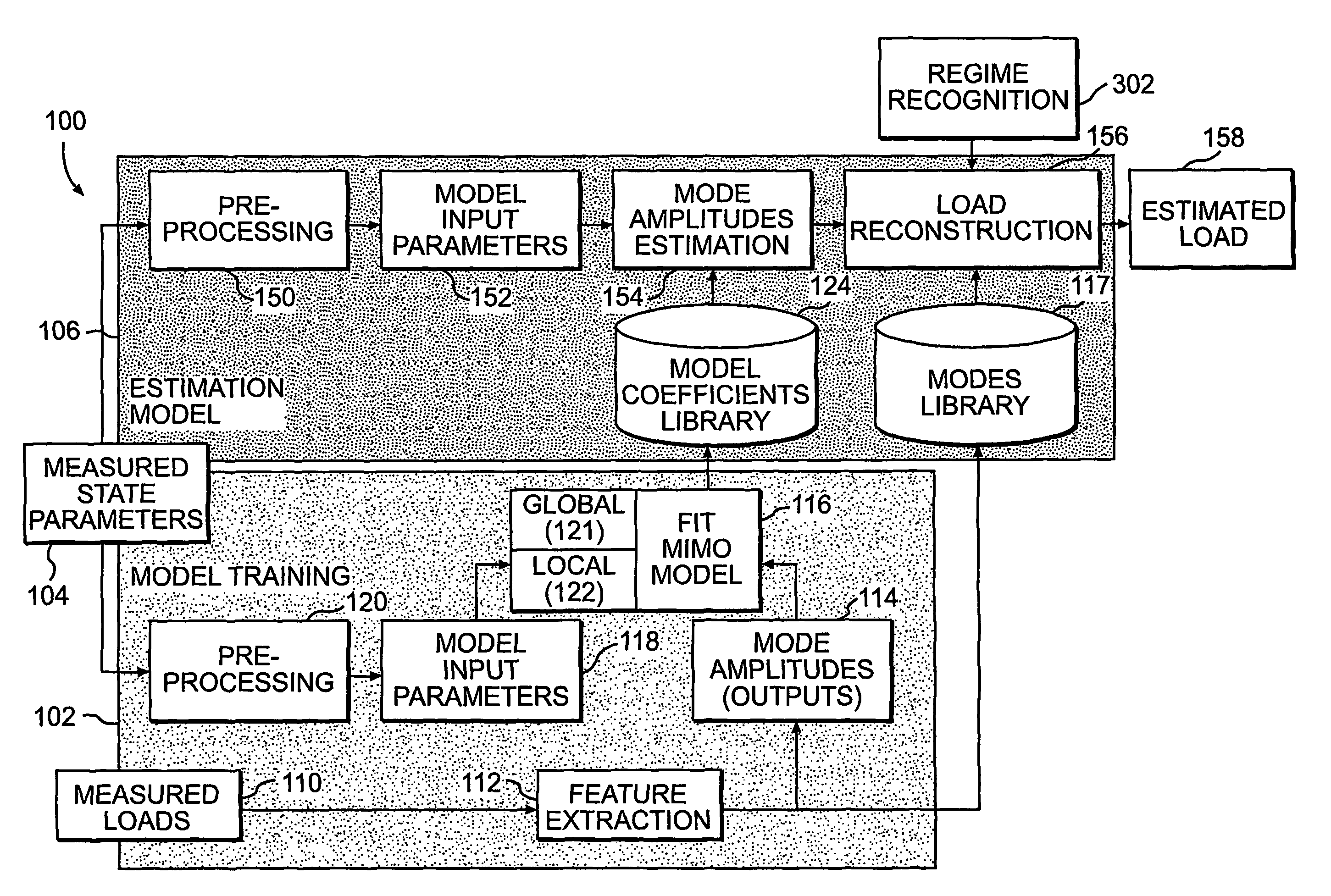
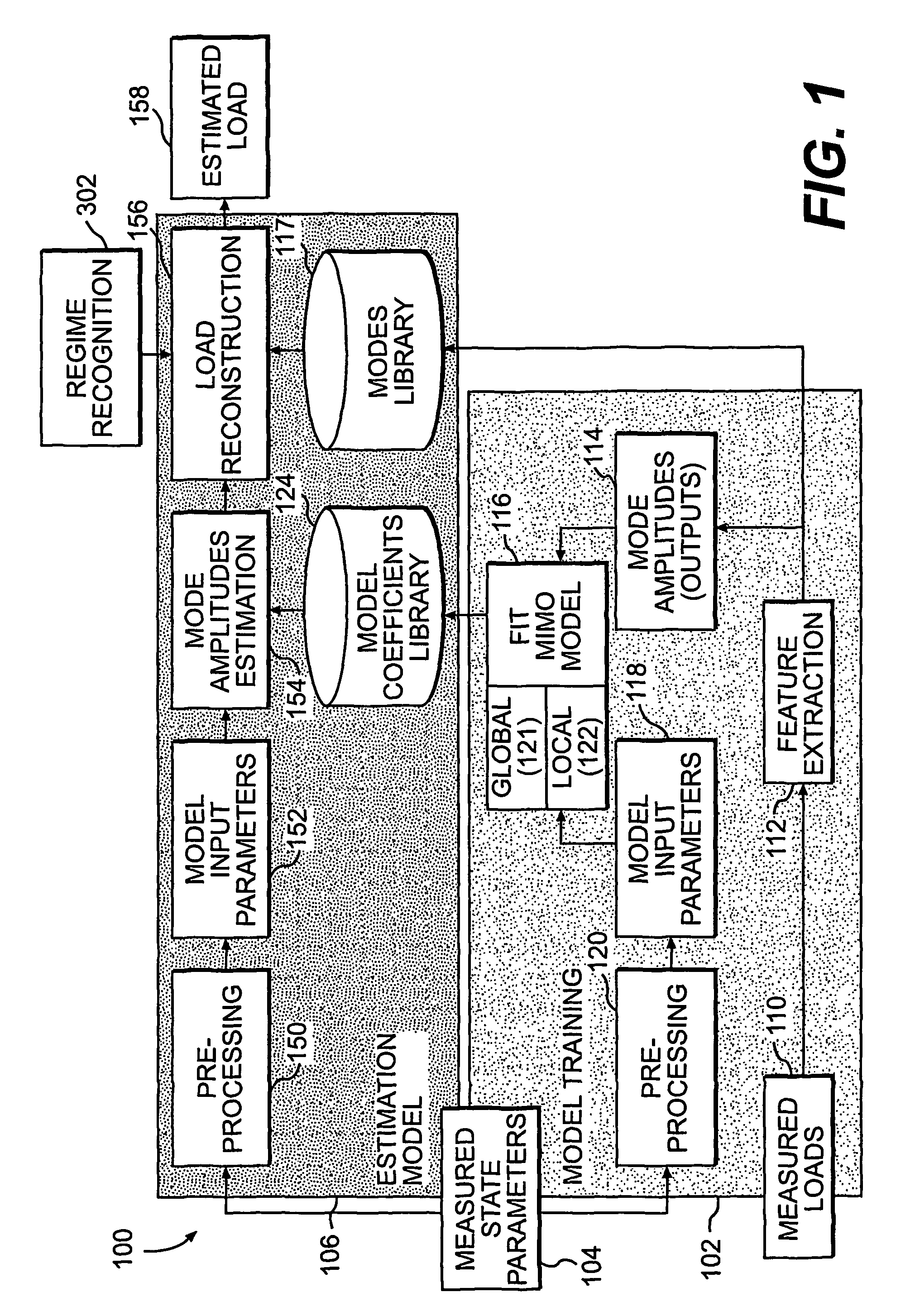
[0016]FIG. 1 illustrates one embodiment of an overall signal estimation process 100 according to one embodiment of the invention. Although the description below focuses on load estimations, it is to be understood that the system and process can be used in any application where accurate signal estimates are desired.

[0017]1. Overview of Signal Estimation Concept

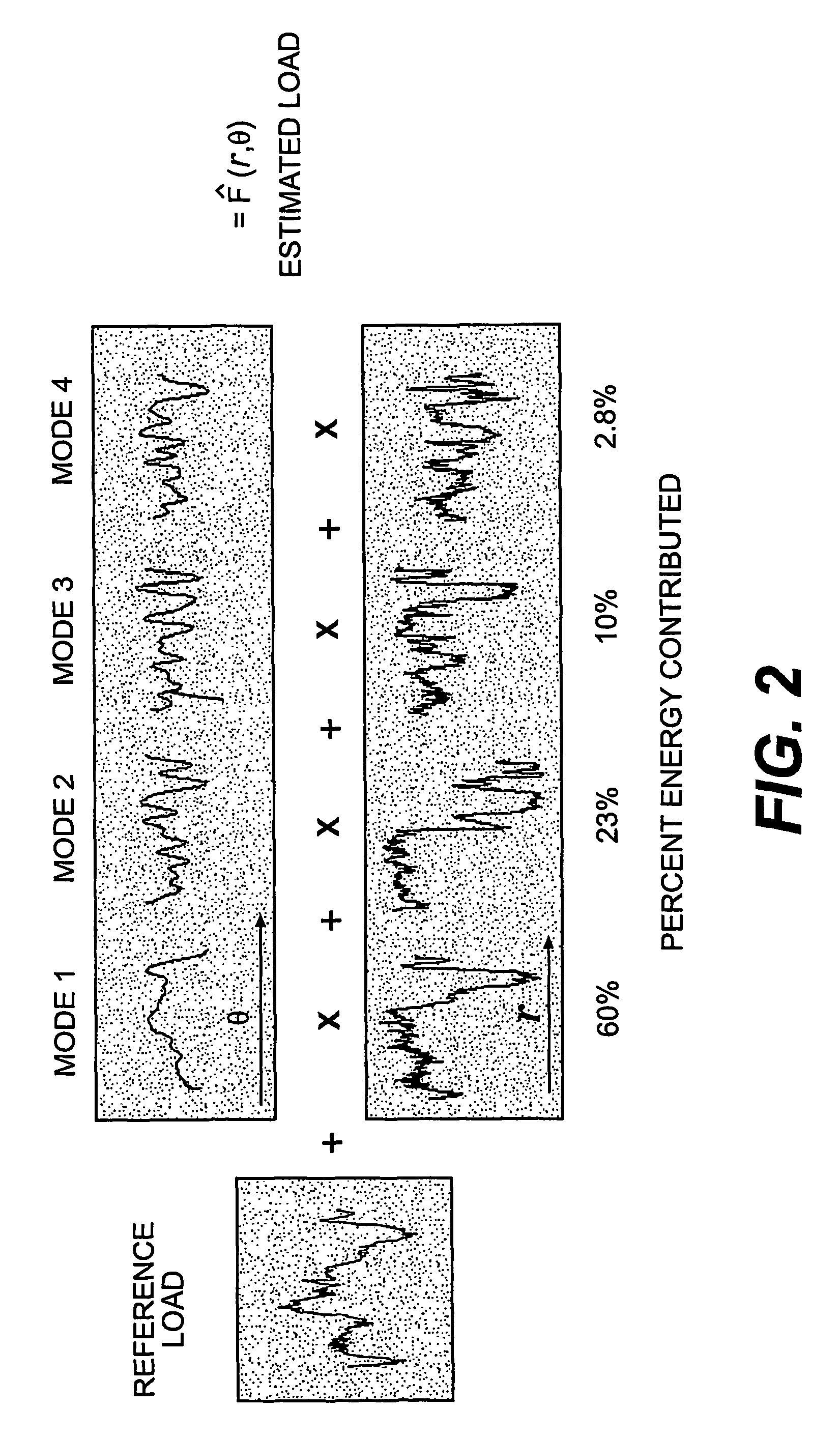
[0018]Data corresponding to loads applied on a part or a part response to a load (collectively referred to as “loads” in this application) provides valuable information on how a component is being used. In many cases, however, it is difficult to obtain accurate load measurements of the part, particularly if the part is rotating or otherwise moving. Although there have been proposed methods for estimating loads generally, they have exhibited various problems.

[0019]Estimation techniques may be categorized according to their estimation capabilities and complexity, such as whether the estimation technique is linear or non-linear, s...


PUM


Abstract

A method and system estimates a desired output signal waveform based on measured state parameters. A model training step generates a model by empirically obtaining measured signal waveforms corresponding to measured state parameters. Features, such as mode shapes and mode amplitudes, are extracted from the measured signals and stored in an estimation model along with coefficients of the model that correlate measured state parameters with the mode amplitudes. During part operation, the state parameters measured during operation are entered into the estimation model to obtain estimated features in a estimated signal waveform. The estimated features are then used to synthesize the estimated signal reflecting the actual operation of the operating part. The estimation model therefore allows estimation of an entire signal waveform from the state parameters.

Description

REFERENCE TO RELATED APPLICATIONS[0001]This application is a 371 of PCT Application No. PCT / US2004 / 025733 filed on Aug. 9, 2004, which claims priority to U.S. Provisional Application No. 60 / 493,198, which was filed on Aug. 7, 2003.TECHNICAL FIELD[0002]The present invention relates to a system and method of monitoring operation of a part experiencing at least one loadBACKGROUND OF THE INVENTION[0003]Many systems experience characteristics having quasi-periodic properties. For example, equipment containing load-bearing parts (e.g., rotorcraft, jet engines, HVAC chillers, electric motors, etc.) are used in many applications. Designers usually use conservative assumptions regarding the loads that the parts will encounter in service. In actual use, however, the parts in the equipment may encounter loads that are greater than anticipated, causing the life of the part to require service or replacement earlier than planned or part failure. Similarly, the part may encounter loads that are sm...

Claims


Application Information

Patent Timeline
Patent Type & Authority Patents(United States)
IPC IPC(8): G01R13/00G05B13/04G01M99/00G05B17/02G05B23/02
CPCG05B13/04G05B17/02G05B19/4065G05B23/0221G05B2219/37249
Inventor KHIBNIK, ALEXANDER I.ATALLA, MAURO JORGEFINN, ALAN M.DAVIS, MARK W.MA, JUNCYCON, JAMESHORBURY, PETER F.BERNHARD, ANDREAS
Owner SIKORSKY AIRCRAFT CORP
Why Eureka
Try Eureka