Cable length sensor

a technology of cable length and sensor, which is applied in the direction of measuring wheels, hoisting equipment, instruments, etc., can solve the problems of short service life, entail a significant effort, and extremely low service life, and achieve the effect of simple plugging

Inactive Publication Date: 2009-05-19
MICRO EPSILON MESSTECHNIK GMBH & CO KG
View PDF13 Cites 4 Cited by
  • Summary
  • Abstract
  • Description
  • Claims
  • Application Information

AI Technical Summary

Benefits of technology

[0018]The core concept of the present invention accordingly lies in a quite particular modular construction of the cable length sensor, namely to the effect that the complete return device can be replaced in an already pre-tensioned, i.e. usable, condition. For this the return device is designed to have modular form. Accordingly the return device is already compressed in the housing so that dismounting as well as mounting of the complete return device, in functional condition, is possible. Accordingly, the return device is shipped, and in given cases stored, in the pre-tensioned state.
[0026]According to the explanations above, the return device can be held by means of the fixing means in the at least slightly pre-tensioned starting position. The fixing means is essentially associated with the second housing section. They act, from outside of the housing, on the axle of the return device and / or on the coupling means so that, on activation of the fixing means, turning of the axle caused by the force of the springs is effectively avoided. With activated fixing means the tension between the housing and the axle can be maintained with interconnection of the springs so that the return device formed with a modular design can be handled independently of the other components of the cable length sensor.
[0027]In concrete terms, it is advantageous if the fixing means comprises at least one arresting pin which extends through the housing wall to the axle of the return device or to the coupling means. In so doing, it is conceivable that the arresting pin is provided at least in some areas with an outer thread so that it can be screwed either into the housing wall or into the axle or into the coupling means. A simple plugging in using a certain clamping action is also conceivable.
[0030]With regard to simple handling of the cable length sensor for the purpose of replacing the return device it is furthermore advantageous if the housing of the cable drum has a greater diameter than the housing of the return device. In the framework of such a development it is possible that the arresting pin of the cable drum projects into it via an end wall of the housing of the cable drum, specifically that end wall that projects above the housing of the return device, so that handling of the arresting pin for blocking the cable drum is possible from outside and in fact even in the case of a flange-mounted return device. Thereby the mounting or dismounting of the return device is aided quite significantly.

Problems solved by technology

A significant disadvantage in the case of these sensor elements is their short service lifetime, which in this respect defines the service lifetime of the entire cable length sensor.
If the cable length sensor is used with very frequent motion, an extremely low short service lifetime is to be expected, since, specifically, damage occurs very frequently, even after a few months.
Instead of replacing the entire cable length sensor, it is also conceivable to replace merely the spring elements of the return device, which, however, entails a significant effort.
It is to be noted that a break in a spring in the return device routinely leads to additional damage, e.g. to a tear in the measuring cable.
Dismounting and mounting on site by unqualified personnel is practically not possible so that a special repair service is necessary.
Among the significant disadvantages are, in particular, also long machine downtimes, since specifically the complete cable length sensor must be removed and a new cable length sensor must be installed, where, due to storing a complete cable length sensor in advance, high storage costs arise.
The defective cable length sensor is customarily sent to the manufacturer, which entails a significant administrative overhead as well as transport costs.
Since the conventional repair of the cable length sensor is very labor-intensive, relatively high repair costs arise.
Additional costs are to be expected in case of consequential damage to the cable length sensor.
A new cable length sensor, always to be stored in advance, is to be installed by skilled personnel, which in accordance with the discussions above, entails significant storage costs for storing a cable length sensor in advance.
The replaced cable length sensor is sent to the manufacturer, due to which, however, costs arise, namely, on the one hand, costs due to administration and, on the other hand, costs due to transport.
The cable length sensor sent to the manufacturer is generally overhauled, which, once again, is labor-intensive.
In the case of prior-art cable length sensors, thus, for example, according to EP 0 778 239 B1 or U.S. Pat. No. 443,888, the spring replacement alone represents an extremely labor-intensive process.
Moreover, for numerous forms of construction there is a quite significant danger of injury due to a spring possibly jumping out of the housing as soon as the housing is opened and the spring of the return device are withdrawn.
The work to be carried out in replacing the spring of the return device is particularly complex, in particular when the cable length sensor has several springs disposed in series or in parallel.
This is probably the most laborious step of the operation since up to 150 spring revolutions are necessary for this.
It is not possible to compress the springs without a special tool.
Moreover, there is the danger that in compressing the springs, errors are made in the permissible number of revolutions, which in turn reduces the service lifetime of the spring or the spring pack.
Furthermore, it is disadvantageous that the work necessary to replace the individual springs is, as a rule, only possible when the complete cable length sensor has been dismounted from the respective system.
This also requires a quite significant investment of time and ultimately causes downtime of the respective machine, system, and so on.

Method used


Image

  • Cable length sensor
  • Cable length sensor

Examples


Embodiment Construction

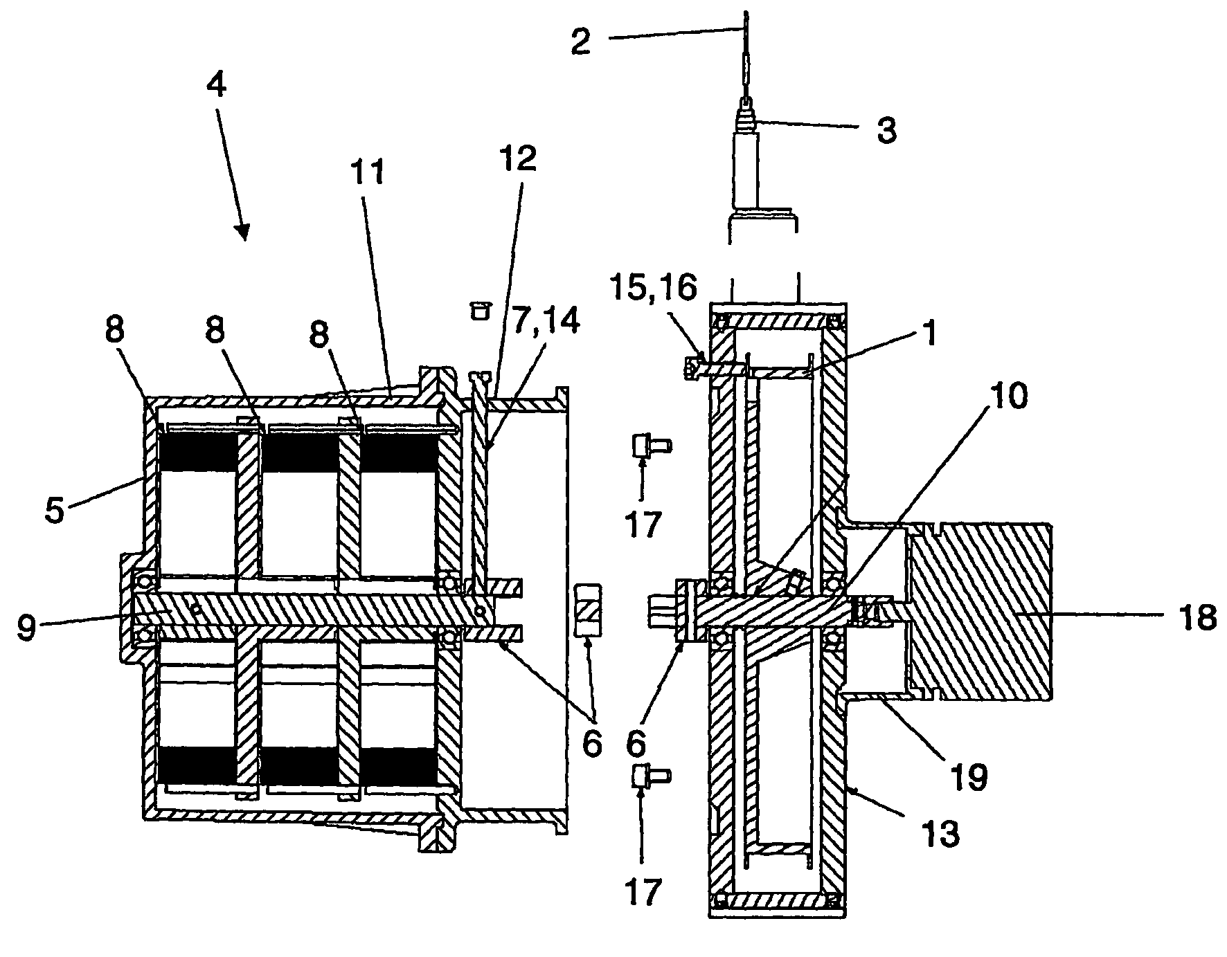
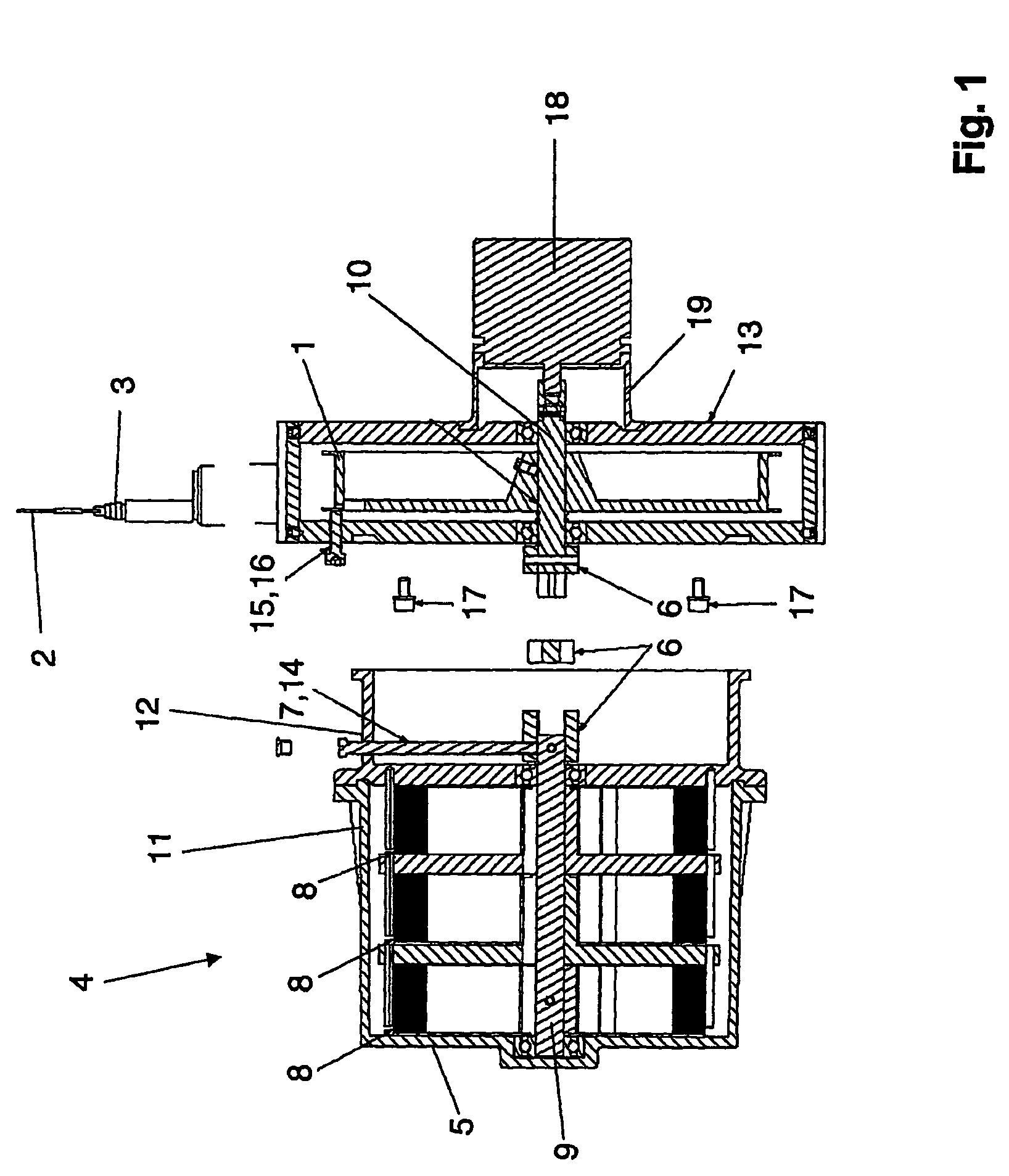
[0037]FIG. 1 shows an exemplary embodiment of a cable length sensor according to the invention with its essential components. The cable length sensor shown here is a concrete example of a Bowden cable displacement sensor. It comprises a cable drum 1 and a measuring cable 2 wound on the cable drum 1, where the measuring cable 2 is only indicated at the measuring cable output 3.

[0038]The cable length sensor furthermore comprises a return device 4 which is at least slightly pre-tensioned in the starting position, where the measuring cable 2 can be drawn off the cable drum 1, against the force of the return device 4, by turning said cable drum and where the return device 4 is further tensioned by drawing off the measuring cable 2.

[0039]According to the invention the return device 4 is disposed in a housing 5. Furthermore, a coupling means 6 is provided which serves to couple the return device 4 to the turning motion of the cable drum 1. A fixing means 7 serves to fix the current positio...


PUM


Abstract

A cable length sensor, in particular, a bowden cable displacement sensor, comprising a cable drum, a measuring cable wound on the cable drum and a return device at least lightly pre-tensioned in the start position, wherein the measuring cable may be withdrawn by rotating the cable drum against the force of the return device and by withdrawing the measuring cable the return device may be further tensioned. The return device is arranged in a housing, and coupling means for releasably coupling the return device to the rotating movement of the cable drum are provided so as to permit ready removal and replacement of the return device. Also, the housing may be provided with a sensor element operated from outside the housing for determining the current position of the return device, in particular the at least lightly tensioned starting position of the return device.

Description

CROSS-REFERENCE TO RELATED APPLICATIONS[0001]The present application is a Continuation of International Application No. PCT / DE2007 / 000347, filed Feb. 23, 2007, and which designates the U.S. The disclosure of the referenced application is incorporated herein by reference.FIELD OF THE INVENTION[0002]The invention relates to a cable length sensor, in particular to a Bowden cable displacement sensor, with a cable drum, a measuring cable wound on the cable drum, and a return device which is pre-tensioned at least slightly in the starting position, where the measuring cable can be drawn off the cable drum, against the force of the return device, by turning said cable drum and where the return device is further tensioned by drawing off the measuring cable.BACKGROUND OF THE INVENTION[0003]At this point let it be noted that the discussion here is in fact of a cable length sensor and accordingly of a cable drum and a measuring cable but, however, the term “measuring cable” is to be understood...

Claims


Application Information

Patent Timeline
Patent Type & Authority Patents(United States)
IPC IPC(8): G01B3/11B66D5/32
CPCB66D5/32G01B3/11
Inventor BIRCHINGER, THOMASHRUBY, JAROSLAV
Owner MICRO EPSILON MESSTECHNIK GMBH & CO KG
Why Eureka
Try Eureka