
Methods and apparatus for accelerating mechanical members associated with a moving subsystem on a mobile X-ray medical imaging system

a technology of moving subsystems and mechanical members, applied in electrical equipment, medical science, diagnostics, etc., can solve the problems of weaker and more troublesome vibration, less robustness, and aggravate the tendency of mobile systems to vibra

Inactive Publication Date: 2009-05-19
GENERAL ELECTRIC CO
View PDF5 Cites 18 Cited by
  • Summary
  • Abstract
  • Description
  • Claims
  • Application Information

AI Technical Summary

Benefits of technology

"The patent describes a method and apparatus for improving the motion of a mobile X-ray medical imaging system. The method involves determining the resonant frequencies of the mechanical members and synthesizing excitation acceleration and deceleration pulses that minimize energy at those frequencies. This reduces vibration in the system and allows for smoother motion. The apparatus includes a motion controller that outputs the necessary pulses to achieve this reduction in vibration. Overall, this technology improves the accuracy and stability of X-ray medical imaging procedures."

Problems solved by technology

In mobile imaging systems, the C-arm and associated members tend to be lighter in weight and are therefore less robust than fixed systems that can aggravate the mobile system's tendency to vibrate.
However, the stronger and more troublesome vibrations tend to be between 0.5 and 5 cycles per second.
Because vibration can cause image blur, detailed imaging requires the x-ray source to output very short high powered x-ray pulses to freeze motion, much as a pulsing strobe light freezes motion when viewed optically, (more expensive and typically impractical due to power constraints for mobile equipment), or that the C-arm member not vibrate during image capture because vibration can cause image blur.
The delay in imaging can also cause additional unnecessary distress to an injured patient who must remain stationary during the imaging process and if numerous images are required, the additional imaging time and the associated distress to the patient caused by the stabilization delay can be significant.
Errors in location can result in reconstruction artifacts for the CT or 3D images.
However, natural mechanical resonances as those described above, can cause unwanted vibrations to occur while the members are in motion during CT or 3D acquisition.

Method used


Image

  • Methods and apparatus for accelerating mechanical members associated with a moving subsystem on a mobile X-ray medical imaging system
  • Methods and apparatus for accelerating mechanical members associated with a moving subsystem on a mobile X-ray medical imaging system
  • Methods and apparatus for accelerating mechanical members associated with a moving subsystem on a mobile X-ray medical imaging system

Examples


Embodiment Construction

[0024]In the following detailed description, reference is made to the accompanying drawings that form a part hereof, and in which is shown by way of illustration specific embodiments that can be practiced. These embodiments are described in sufficient detail to enable those skilled in the art to practice the embodiments, and it is to be understood that other embodiments can be utilized and that logical, mechanical, electrical and other changes can be made without departing from the scope of the embodiments. The following detailed description is, therefore, not to be taken in a limiting sense.

Method Embodiments

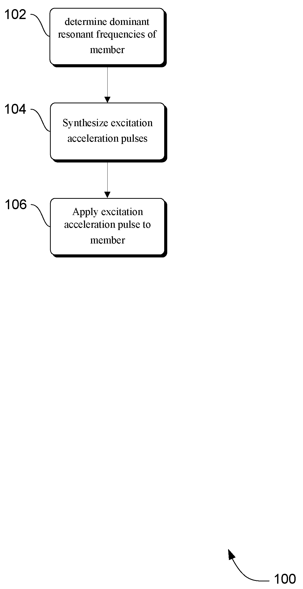
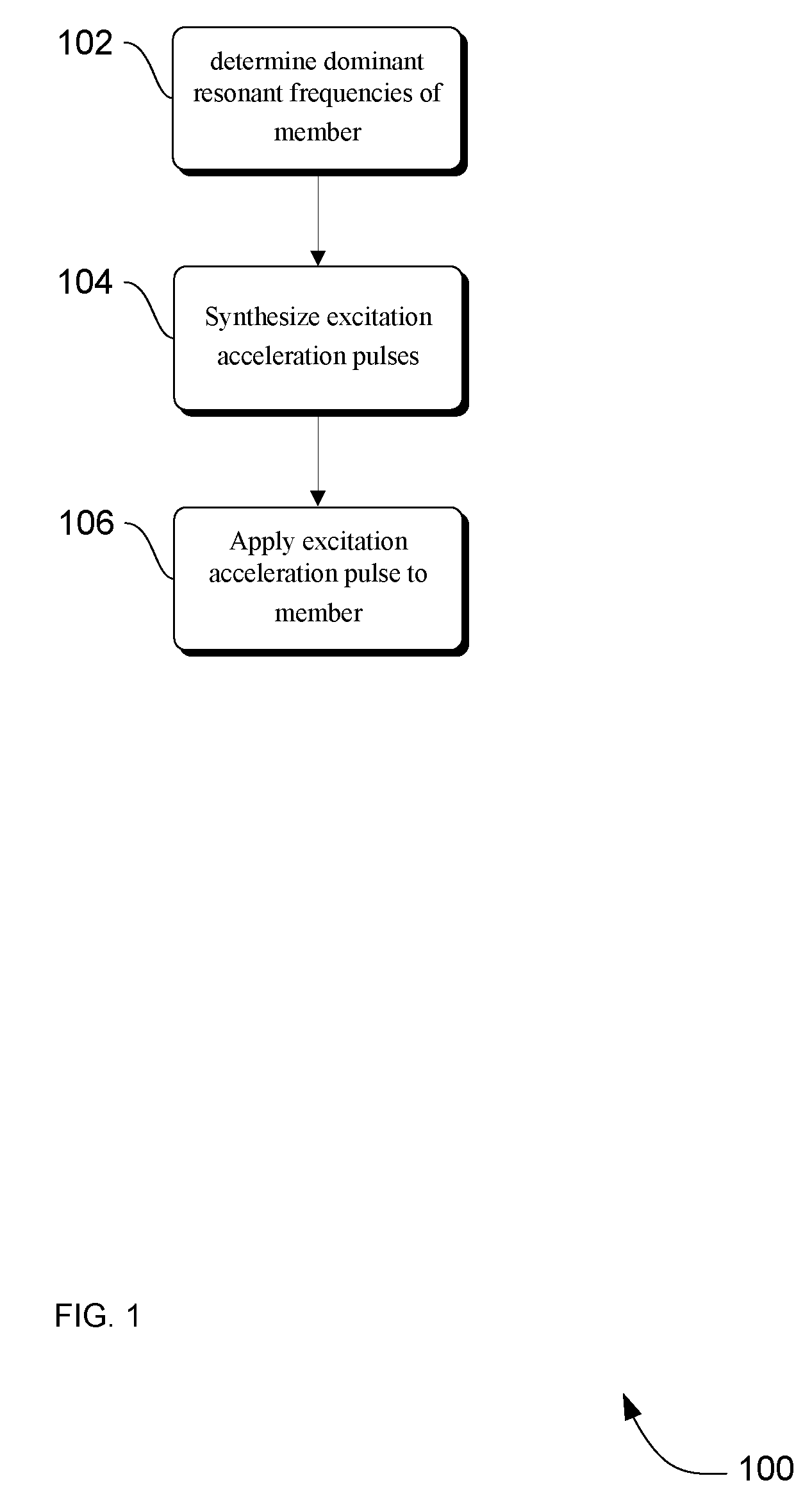
[0025]FIG. 1 illustrates a method 100 for accelerating mechanical members associated with a moving subsystem on a mobile X-ray medical imaging system without providing excitation energy that will cause unwanted vibrations in accordance with an embodiment. In action 102, the resonant frequencies of the member desired to be accelerated are determined. According to an embodiment, ...


PUM


Abstract

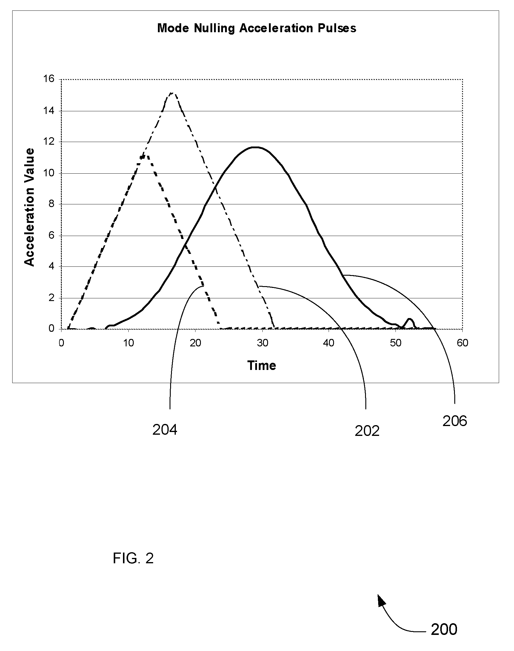
Methods and apparatus are provided through which mechanical members associated with a moving subsystem on a mobile X-ray medical imaging system are accelerated and decelerated using triangular acceleration and deceleration pulses having pulse widths that do not provide excitation energy that will cause unwanted vibrations in the members.

Description

FIELD OF THE INVENTION[0001]This invention relates generally to mobile X-ray medical imaging systems, and more particularly to mobile X-ray medical imaging systems which contain powered motion control for accelerating mechanical members associated with a moving subsystem.BACKGROUND OF THE INVENTION[0002]Modern medical X-ray imaging systems have become a valuable tool in the healthcare profession. Imaging systems such as basic X-ray, computed tomography (CT) and fluoroscopy systems which were once found only in major medical facilities have become more commonplace due to their affordable cost and compact size. Oftentimes, mobile X-ray imaging systems are utilized outside of radiology rooms because of their ability to be transported to operating rooms or other areas serving multiple purposes, thus providing instant on-the-spot X-ray imaging.[0003]Mobile X-ray medical imaging systems often contain various mechanical members that are typically long and slender in shape. On a typical mob...

Claims


Application Information

Patent Timeline
Patent Type & Authority Patents(United States)
IPC IPC(8): H05G1/02
CPCA61B6/4405A61B6/4476
Inventor CURTIS, STEVEN EMERSON
Owner GENERAL ELECTRIC CO
Learn More