Customized electronic display and methods of customizing the physical size and/or shape thereof

a technology of electronic display and customization, applied in non-linear optics, instruments, optics, etc., can solve the problems of affecting the operation of the display, the physical size and/or shape of the display is reduced, and the modification cannot be made without disturbing the surrounding instruments, etc., to achieve the effect of enhancing the functionality of the display, reducing the physical size and/or shape, and enhancing the functionality

Inactive Publication Date: 2009-05-19
PIXEL SCI
View PDF24 Cites 36 Cited by
  • Summary
  • Abstract
  • Description
  • Claims
  • Application Information

AI Technical Summary

Benefits of technology

[0011]The present invention involves systems and methods for customizing a COTS display by modifying the physical size and / or shape of the COTS display to meet the requirements of a target application. This is accomplished by cutting the physical COTS display to reduce its physical size and / or shape, and then resealing the display to achieve the desired performance. The basic functionality of the COTS display remains intact. That is, the customized display will have a new size and / or shape, and may have altered electronic drivers, image-generating media, rearranged electronics, additional seals, additional films, etc., and may actually have enhanced functionality. However, the customized display will be able to operate in a target application designed to interface with a display of the same type (e.g., AMLCD) as the original (e.g., COTS) display.
[0012]When the plates are cut, internal electronics might also be cut, often requiring reestablishment of electrical continuity. Similarly, the display electronics may be removed, reattached, or otherwise modified, and filters, polarizers, and / or other films associated with the display and typically attached externally to the plates may be cut, to conform to the customized display size and / or shape. Thus the opportunity exists to add enhanced functionality to the display. A custom bezel and frame may then be used to house the display, allowing for additional ruggedization of the entire unit.
[0013]To reseal the display, an adhesive is applied along at least the cut edge or edges. A second seal may be added to minimize the penetration of humidity and other contaminants into the display media (e.g., liquid crystal material) inside the display cell. A third seal serving as a mask may also be applied to prevent back light typically used with LCDs from passing through the display around the outer edges of the display image area.
[0014]Electronic drivers, typically VLSI circuits (bonded to TAB substrates attached to the display, or attached directly to the display as COG) may be added, repositioned and / or reattached as needed, and the circuitry on the display plates may be altered to make electrical connection to the new VLSI circuits. Filters, films, polarizers, etc., may then be cut and / or installed as desired, and additional components such as heaters, optical elements, infrared filters, touch panels, transducers, etc., may be added to alter and / or enhance durability or functionality of the display.
[0016]One aspect of the present invention thus involves customizing an electronic display by cutting the display along desired dimensions resulting in a target display portion and an excess display portion, and applying a first seal between the plates along an exposed edge of the target display portion, said first seal creating a barrier to prevent the image-generating medium from escaping out of the area between the plates, wherein the basic functionality of the display remains intact. A second seal and / or a third seal may be added.

Problems solved by technology

The displays and their associated bezels (face plates) and frames (interfacing and supporting hardware) are typically built to demanding specifications for durability, reliability, and operating life, due to industry requirements, and the resulting displays have relatively complex electrical, chemical, optical, and physical characteristics.
Due to the high costs associated with such varying and demanding specifications, for any particular application it is thus economically necessary for manufacturers to produce a common design in high production volume, resulting in COTS displays all having substantially the same characteristics for a variety of physical sizes.
For most applications, however, such modifications cannot be made without disturbing the surrounding instruments, controls, and displays already incorporated into the control panel.
And even if the appropriate modifications could be made, they are typically cost-prohibitive.
Since a completed electronic display is delicate and relatively complex, most experts in the filed would not expect that customization of the displays as desired could be accomplished by physically cutting an original display, changing its size and / or shape, and resealing it, while maintaining its same basic functionality.

Method used


Image

  • Customized electronic display and methods of customizing the physical size and/or shape thereof
  • Customized electronic display and methods of customizing the physical size and/or shape thereof
  • Customized electronic display and methods of customizing the physical size and/or shape thereof

Examples


Embodiment Construction

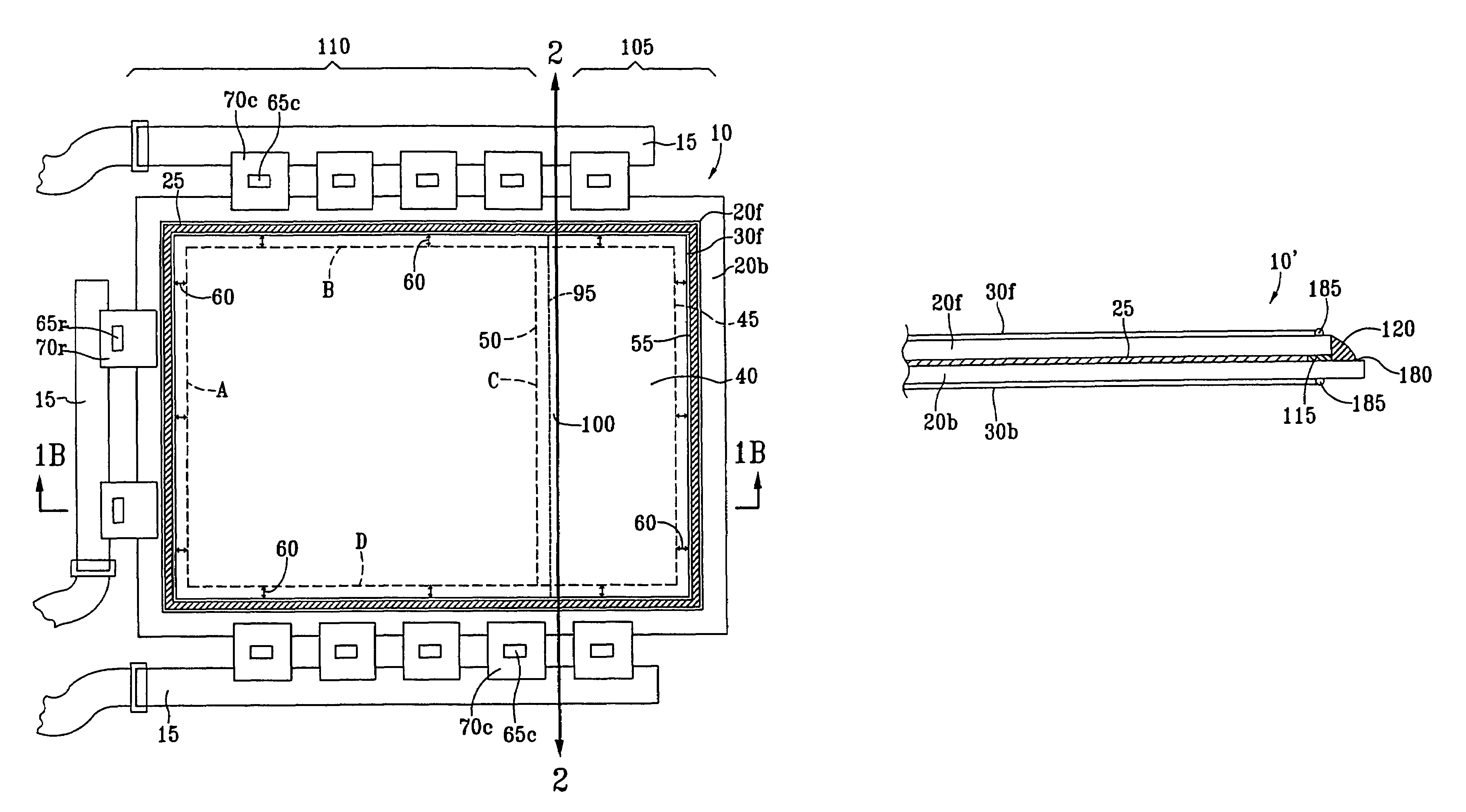
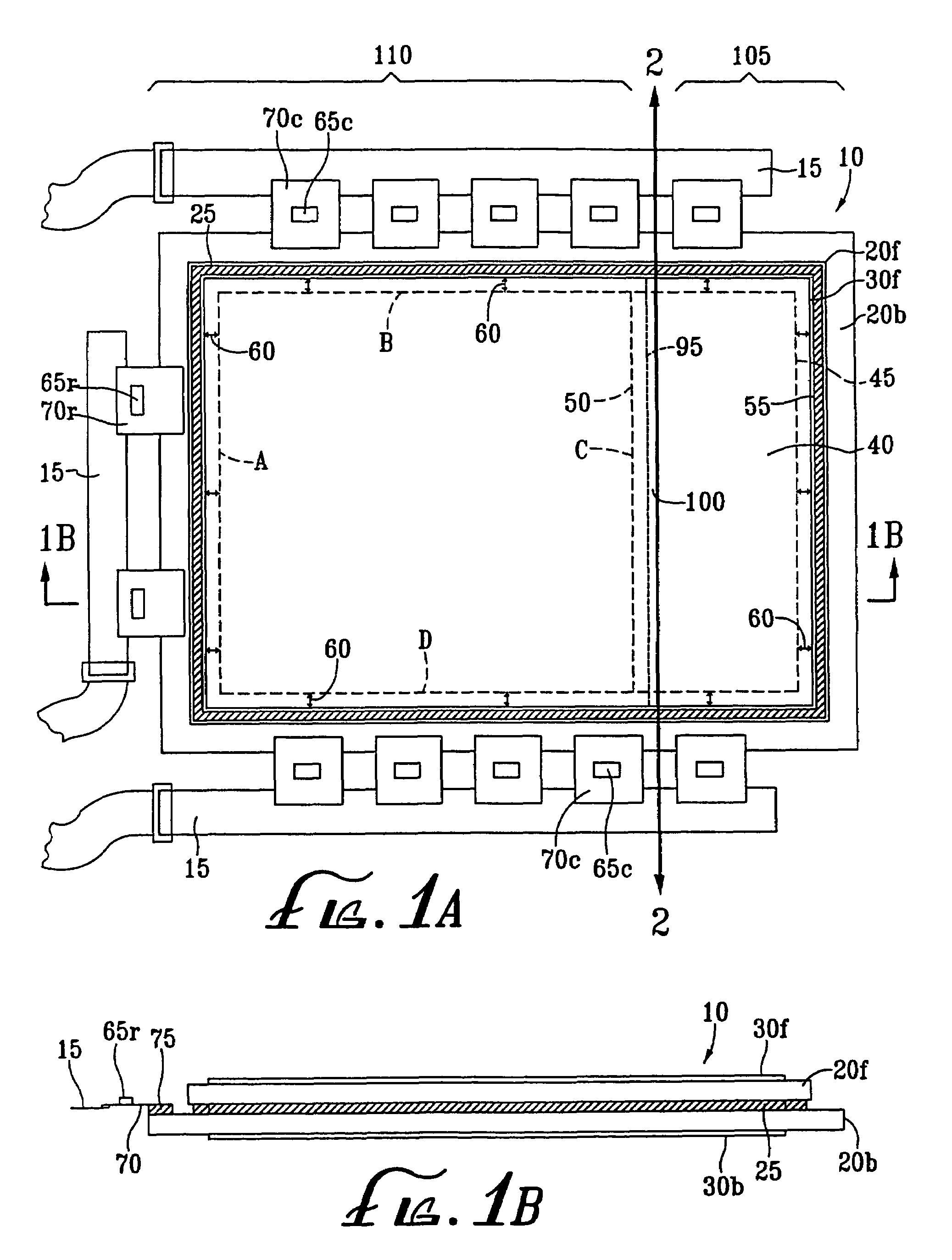
[0028]FIGS. 1A and 1B show a typical rectangular, non-square COTS AMLCD 10, before resizing and / or reshaping, but after disassembly from its original bezel, frame, and other associated hardware and electronics. The external components associated with the display 10 other than the circuit boards 15 and the components bonded or attached to the display plates 20f and 20b, have been removed for clarity. Such external components would preferably be removed prior to performing the customization of the display 10 as described herein.

[0029]The display 10 comprises a front plate 20f and a back plate 20b, each preferably made of glass or plastic. The plates 20 are held together by a perimeter seal 25 such as a UV curing urethane as is known in the art, and are also typically further secured within a bezel (not shown) which is in turn secured to a frame or other hardware (not shown) for attachment to the target location. Polarizing films 30f and 30b, filters (not shown), image enhancement film...


PUM

PropertyMeasurementUnit
physical shapeaaaaaaaaaa
areaaaaaaaaaaa
thicknessaaaaaaaaaa

Abstract

Electronic displays are physically reshaped and / or resized to meet custom specifications for special applications such as avionics, where Commercial Off-The-Shelf (COTS) Liquid Crystal Displays (LCDs) are not typically used. Customization includes cutting the physical display to specified dimensions to fit into a target opening, and resealing the display to preserve proper cell spacing and assure basic functionality. The target opening is typically a control panel or dashboard opening, such as in the cockpit of an airplane. The sealing process may include improving the original seal, and / or providing additional seals. Additional seals may protect sensitive areas against chemical corrosives or contamination, humidity, electrostatic damage, etc., and / or prevent light from passing around the edge of the display image area. Electric continuity may need to be reestablished for electric leads affected during the customization process, and electronic drivers may need to be reattached to the display. Additional modifications and / or enhancements may be made to the display during reshaping and / or resizing. For example, TABs or COGs may be relocated, added, removed, replaced, and / or reoriented; electric circuits may be replaced and / or supplemented with circuits having different functionality; the display medium may be altered and / or replaced; polarizers, filters, and / or films may be added, removed, and / or replaced. The customized display may then be ruggedized by attaching a suitable bezel (face plate) and frame (support hardware) thereto, and the completed, customized display unit may then be installed in the target location and integrated with surrounding hardware and electronics.

Description

[0001]This application is a continuation of application Ser. No. 10 / 103,473, filed Mar. 20, 2002, which is a continuation of Ser. No. 09 / 812,370, filed Mar. 16, 2001, now U.S. Pat. No. 6,380,999, which is a continuation of application Ser. No. 09 / 274,427, filed Mar. 22, 1999, now U.S. Pat. No. 6,024,906, on Mar. 20, 2001.FIELD OF THE INVENTION[0002]The present invention relates generally to electronic displays, and more particularly to the customization of an original display by physical alteration of the size and / or shape thereof, such that the customized display may be used in installations not considered achievable with the original display.DEFINITIONS[0003]In this application, COTS is used as an acronym for “Commercial Off-The-Shelf”; FPD is used as an acronym for “Flat-Panel Display”; LCD is used as an acronym for “Liquid Crystal Display”; PDLC is used as an acronym for “Polymer-Dispersed Liquid Crystal”, AMLCD is used as an acronym for “Active Matrix Liquid Crystal Display”; T...

Claims


Application Information

Patent Timeline
Patent Type & Authority Patents(United States)
IPC IPC(8): G02F1/1339G02F1/1333
CPCG02F1/1339G02F1/133308G02F1/133351G02F2001/133314G02F2001/13332G02F2001/133325G02F1/13332G02F1/133314G02F1/133325
Inventor TANNAS, JR., LAWRENCE E.
Owner PIXEL SCI
Why Eureka
Try Eureka