Method to determine a feedback threshold in a hearing device

a hearing device and feedback threshold technology, applied in the field of signal processing in hearing devices, can solve the problems of inability to use the hearing device, poor hearing quality, and noise of the hearing device, so as to improve the quality of the hearing device and/or the quality of the hearing. the effect of no efficient feedback cancellation

Inactive Publication Date: 2009-05-19
SONOVA AG
View PDF9 Cites 14 Cited by
  • Summary
  • Abstract
  • Description
  • Claims
  • Application Information

AI Technical Summary

Benefits of technology

[0019]It has already been pointed out that knowledge of the feedback threshold gain is of great importance. This is in particular true if the hearing device disposes over no efficient feedback canceling. But also in the case where a feedback canceling is available, knowledge of the feedback threshold is of great value. Thus, by the present invention, a possibility is given to improve the quality of the hearing device and / or the quality of the hearing, in particular for an in-the-ear device (ITE).
[0020]Furthermore, the present invention has at least one of the following advantages:
[0024]For a given surround noise and for the same sound pressure at the ear during the determination of the feedback threshold gain, a higher maximum gain can be reached by the present invention;

Problems solved by technology

The mentioned effects can result in a squealing for hearing devices, which squealing is very uncomfortable for the hearing device user and finally renders the hearing device unusable during the occurrence of the squealing.
Therewith, the use of a hearing device is compromised, to be precise in particular for those applications, by which a large hearing loss must be compensated as it occurs for a person who is hard of hearing, because for such patients a comparatively large gain in the hearing device must be adjusted in order to obtain an adequate compensation.
Furthermore, an additional microphone is being used for this variant, which is based on an in-situ measurement, by which the acoustical but also the mechanical characteristics of the overall system is being changed in a disadvantageous manner, such that, as a consequence thereof, errors will occur in the further calculations to determine the feedback threshold.
It is an integrated signal feedback damping which has an influence on the overall transfer function of the hearing device partly in an undesirable manner because signal components of the desired signal are being damped at the same time.
This simple method has the great disadvantage that the hearing device user is exposed to high sound levels.

Method used


Image

  • Method to determine a feedback threshold in a hearing device
  • Method to determine a feedback threshold in a hearing device
  • Method to determine a feedback threshold in a hearing device

Examples


Embodiment Construction

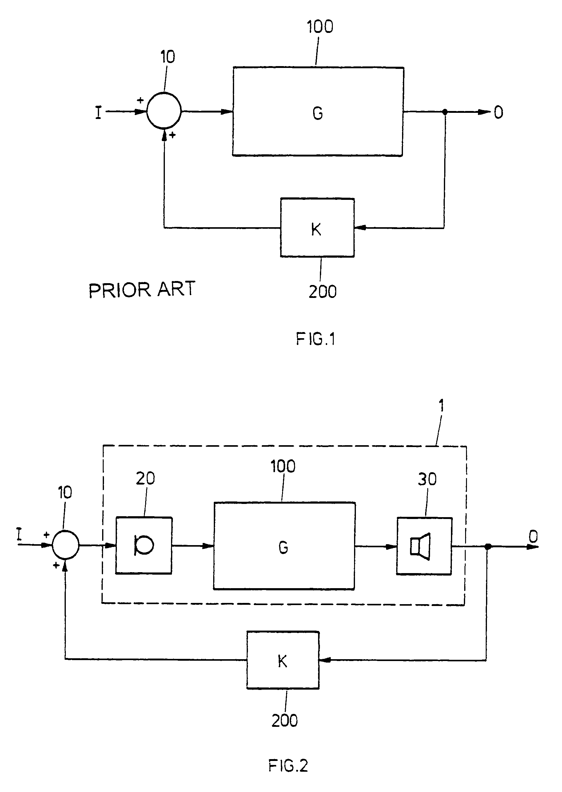
[0032]FIG. 1 shows a block diagram for a feedback system as it is generally known. By 100, a processing unit having a transfer function G, and, by 200, a feedback unit having a transfer function K are identified. An input signal I is fed to one of the two inputs of an addition unit 10 of which the only output is fed to the processing unit 100. In the processing unit 100, an output signal O is generated that is fed to the second input of the addition unit 10 via the feedback unit 200, besides the circumstance that the output signal O is fed to the outside.

[0033]Having identified the transfer function in the forward and in the backward path by G and K, respectively, the following overall transfer function for the system according to FIG. 1 can be obtained as follows:

[0034]OI=G1-K·G

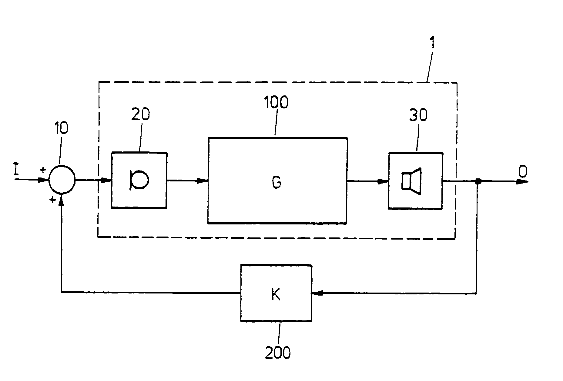
[0035]FIG. 2 schematically shows a block diagram of a hearing device 1, comprising a processing unit 100 with a transfer function G. Seen from a propagation direction of signals in the hearing device, a loud...


PUM


Abstract

Provided is a hearing device and method for compensating for a hearing loss. To compensate for the hearing loss, the hearing device and method utilize the gain during feedback in the forward path of a compressive system which, after having reached its steady state in “closed loop” operation, is equal to the feedback threshold gain. The steady state is reached soon after having applied a low input signal level to the hearing device, which input signal level is below 55 dB SPL (Sound Pressure Level), for example, and would result, for the open loop compressive system, in a larger gain than the feedback threshold gain of the closed loop system, respectively, would result in the maximum possible hearing device gain if maximum possible hearing device gain is below feedback threshold gain. The signal feedback gain is assessed in this steady state.

Description

CROSS-REFERENCE TO RELATED APPLICATIONS[0001]This application is a Continuation-In-Part of U.S. application Ser. No. 10 / 263,126 filed Oct. 2, 2002.TECHNICAL FIELD[0002]This invention relates to the field of signal processing in hearing devices, and more particularly to a method to determine a feedback threshold in a hearing device.BACKGROUND OF THE INVENTION[0003]Hearing devices are electronic devices in which sound is recorded by a microphone, is processed or amplified, respectively, in a signal processing unit, and is transmitted into the ear canal of a hearing device user over a loudspeaker which is also called receiver. The amplified or processed sounds which are emitted by the receiver are partially recorded by the microphone. In other words, it must be dealt with a closed loop comprising a hearing device with an output signal and an input signal. It must be noted that the path of the sound energy is not limited to acoustic energy, but also comprises, as the case may be, a mech...

Claims


Application Information

Patent Timeline
Patent Type & Authority Patents(United States)
IPC IPC(8): H04R25/00H04R29/00
CPCH04R25/30H04R25/453H04R25/70
Inventor VON BUOL, ANDREAS
Owner SONOVA AG
Why Eureka
Try Eureka