
Pneumatic tire with wound cord layer between carcass layer and belt layers

a technology of pneumatic tires and cord layers, applied in the field of pneumatic tires, can solve problems such as easy damage to the cord layer, and achieve the effects of reducing the durability of the tire, improving the durability of the pneumatic tire, and providing moistur

Inactive Publication Date: 2009-05-26
THE YOKOHAMA RUBBER CO LTD
View PDF6 Cites 6 Cited by
  • Summary
  • Abstract
  • Description
  • Claims
  • Application Information

AI Technical Summary

Benefits of technology

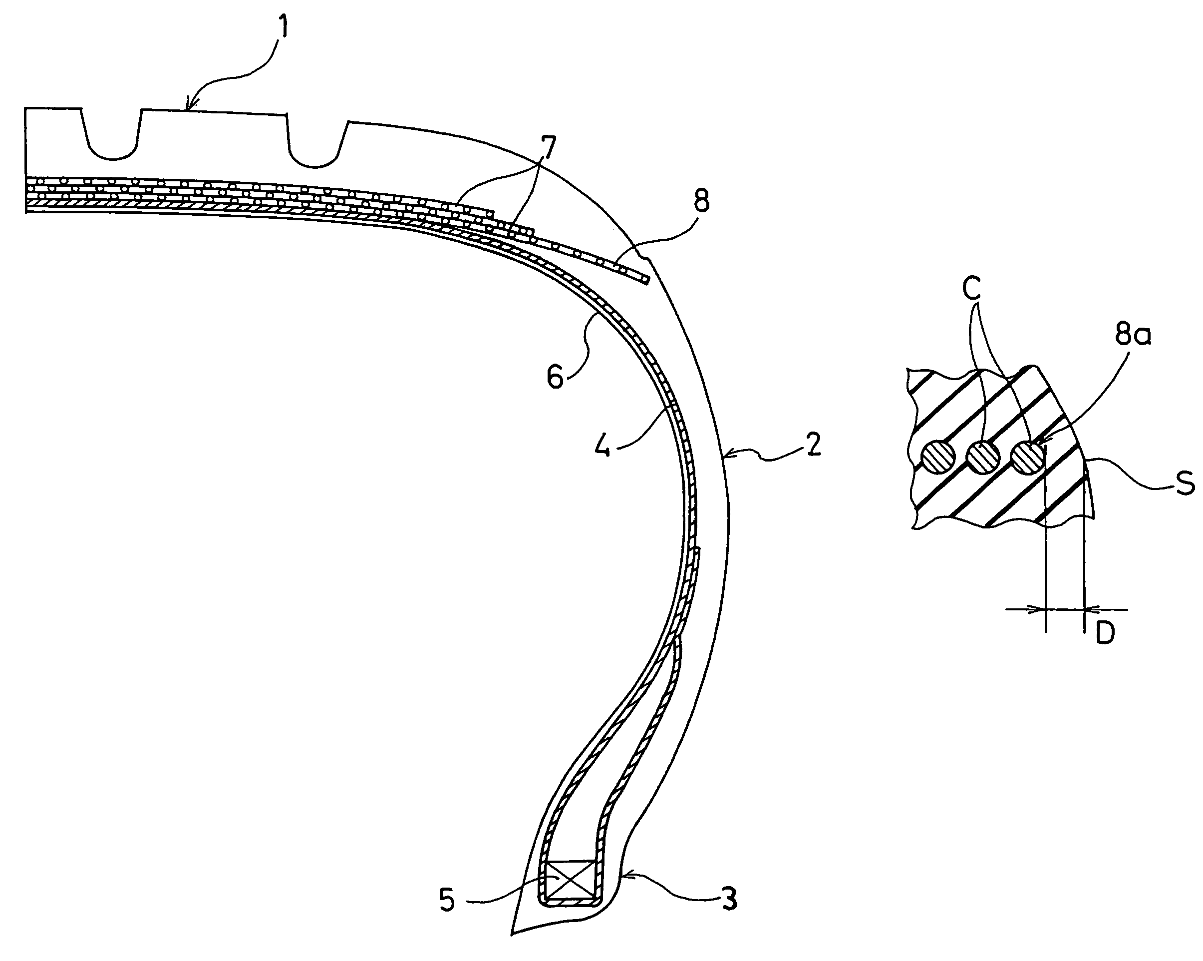
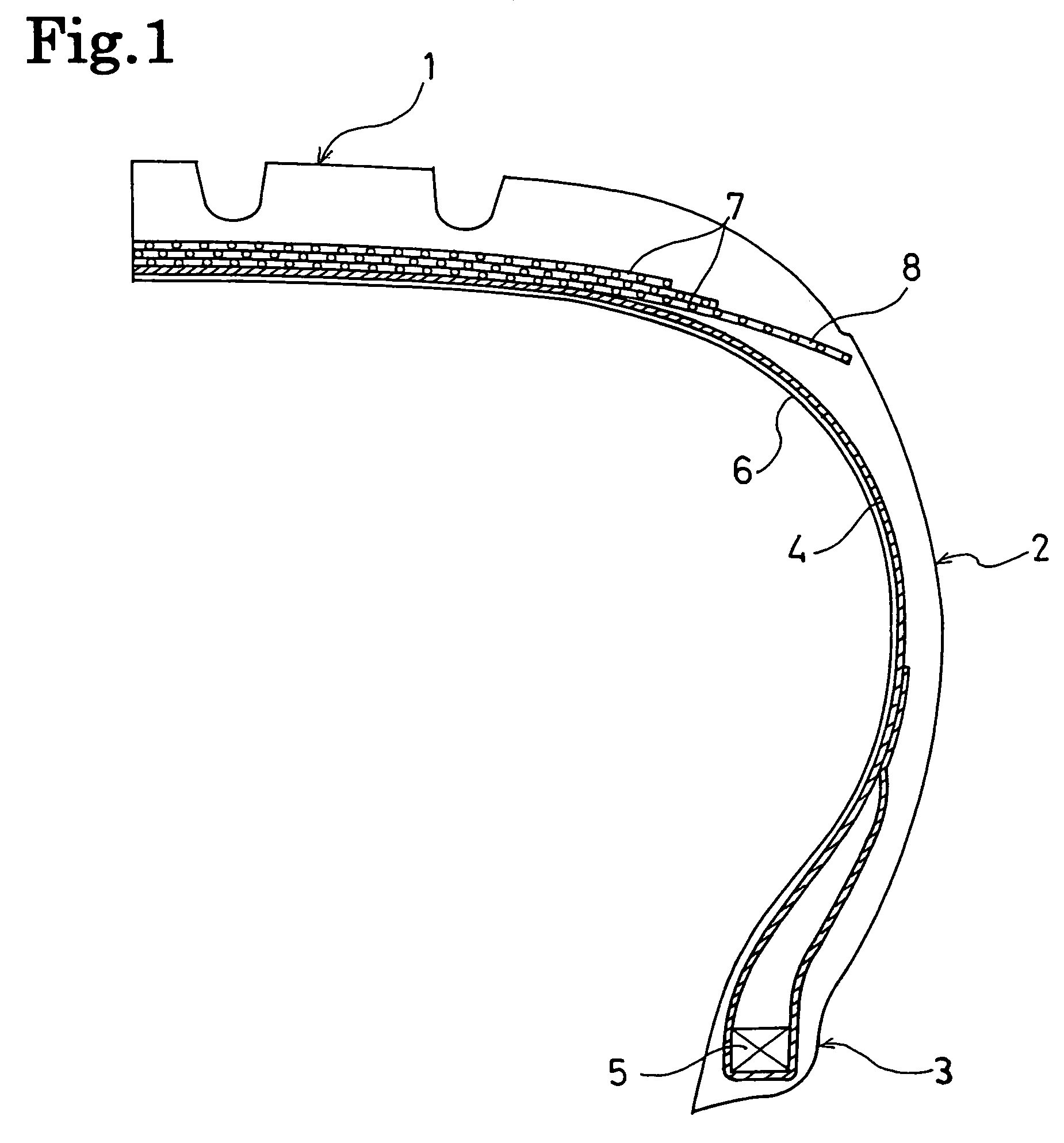
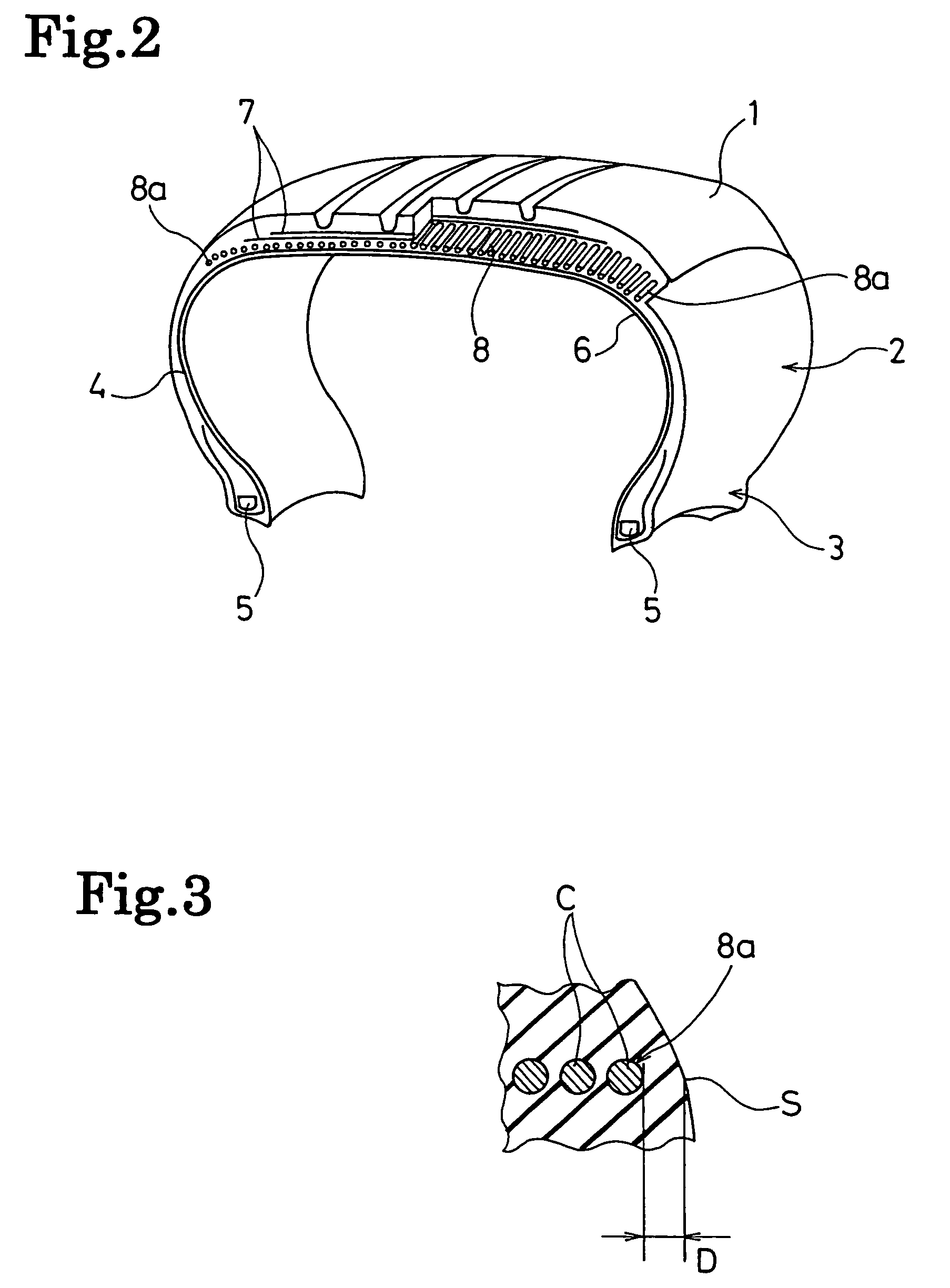
The present invention provides a pneumatic tire with improved durability by preventing oxidation degradation of belt layers. This is achieved by placing a cord layer between the carcass layer and the belt layers, with at least one portion of the cord layer close to the outer surface of the tire. The cord layer prevents air from reaching the belt layers and discharges the air to the outside of the tire, reducing the amount of oxygen passing through the belt layers. The cord layer is designed to have a configuration in which the cord is repeatedly wound in the tire circumferential direction, which prevents damage to the cord layer and ensures the supply of moisture to the belt layers. The width of the cord layer and the belt layers overlap should be at least 10 mm to securely protect the belt layers from separation damage.

Problems solved by technology

In the case where a cord layer has the structure in which a cord is repeatedly wound in the tire circumferential direction, since almost no cord terminal exists, the cord layer is prone to occur damage from a portion of the cord layer close to the outer surface of the tire, even though the cord layer is made close to the outer surface of the tire.

Method used


Image

  • Pneumatic tire with wound cord layer between carcass layer and belt layers
  • Pneumatic tire with wound cord layer between carcass layer and belt layers
  • Pneumatic tire with wound cord layer between carcass layer and belt layers

Examples


example

[0025]Pneumatic tires of a conventional example, a comparative example and an example were prepared. Each of the tires had a tire size of 195 / 65R15, and the tires respectively had structures different from one another.

[0026]In the tire of the conventional example, belt layers were buried in a tread portion at the side of the outer periphery of a carcass layer, and an air penetration preventing layer is provided to the inner surface of the tire. The tire of the comparative example had the structure same as that of the conventional example except the following point. Cord layers were disposed between the carcass layer and the belt layers in buttress portions, the cord layers each formed by disposing a plurality of cords at an angle of 90 degrees to the tire circumferential direction. One of the two ends of each of the cord layers was made close to the outer surface of the tire so that a distance between the cords and the outer surface of the tire was 1 mm.

[0027]The tire of the example...


PUM

PropertyMeasurementUnit
distanceaaaaaaaaaa
widthaaaaaaaaaa
angleaaaaaaaaaa

Abstract

A pneumatic tire is provided which enables durability thereof to be improved by preventing oxidation degradation of belt layers. In the pneumatic tire, a carcass layer is laid between a pair of bead portions so that the carcass layer links the bead portions, an air penetration preventing layer is disposed on the inner surface of the tire along the carcass layer, and belt layers are buried in a tread portion at the side of the outer periphery of the carcass layer. In the pneumatic tire, a cord layer, which is formed by repeatedly winding a cord in the tire circumferential direction, is disposed between the carcass layer and the belt layers, and at least one portion of the cord layer is made close to the outer surface of the tire so that a distance between the cord and the outer surface of the tire is not longer than 2 mm.

Description

BACKGROUND OF THE INVENTION[0001]1. Field of the Invention[0002]The present invention relates to a pneumatic tire in which belt layers are buried in a tread portion, and more particularly to a pneumatic tire which enables durability thereof to be improved by preventing oxidation degradation of the belt layers.[0003]2. Background Art[0004]Separation between a cord and coating rubber at ends of the belt layers in the axial direction of the tire can be cited as one example of a cause of decrease in durability of a pneumatic tire in which the belt layers are buried in a tread portion. Particularly, the deterioration of the belt layers tends to cause the separation between a cord and coating rubber. It has been pointed out that, because oxygen in the air oxidizes coating rubber of belt layers, such deterioration of belt layers is accelerated in a process, in which air in a tire leaks from the tire.[0005]From this viewpoint, inhibiting of oxidation degradation of coating rubber of belt la...

Claims


Application Information

Patent Timeline
Patent Type & Authority Patents(United States)
IPC IPC(8): B60C9/22B60C13/00
CPCB60C9/2009B60C9/2204Y10T152/10783
Inventor MATSUDA, JUNHASHIMURA, YOSHIAKI
Owner THE YOKOHAMA RUBBER CO LTD
Learn More