Doppler ultrasound method and apparatus for monitoring blood flow

a technology of doppler ultrasound and blood flow, which is applied in the field of medical monitoring and diagnostic procedures and devices, can solve the problems of user's ultrasound equipment finding it rather difficult to locate these particular windows or properly orient the ultrasound probe, and user's ultrasound equipment finding it difficult to properly orient and position an ultrasound transducer or probe on the patient. the user does not know if he is looking in the correct direction

Inactive Publication Date: 2009-05-26
SPENTECH
View PDF55 Cites 109 Cited by
  • Summary
  • Abstract
  • Description
  • Claims
  • Application Information

AI Technical Summary

Problems solved by technology

Typically, a user of ultrasound equipment finds it rather difficult to properly orient and position an ultrasound transducer or probe on the patient, as well as to select a depth along the ultrasound beam corresponding to the desired location where blood flow is to be monitored.
The user of the ultrasound equipment may find it difficult to locate these particular windows or to properly orient the ultrasound probe once the particular window is found.
Commonly, the user does not know if he is looking in the correct direction at the wrong depth, the wrong direction at the right depth, or whether the ultrasound window is too poor for appreciating blood flow at all.
Proper location and orientation of the Doppler ultrasound probe, and the proper setting of depth parameters, is typically by trial and error.
Not only does this make the use of Doppler ultrasound equipment quite inconvenient and difficult, it also creates a risk that the desired sample volume may not be properly located, with the corresponding diagnosis then being untenable or potentially improper.

Method used


Image

  • Doppler ultrasound method and apparatus for monitoring blood flow
  • Doppler ultrasound method and apparatus for monitoring blood flow
  • Doppler ultrasound method and apparatus for monitoring blood flow

Examples


Embodiment Construction

[0024]The following describes a novel method and apparatus for providing Doppler ultrasound information to a user, such as in connection with measuring blood velocities to detect hemodynamically significant deviations from normal values, and to assess blood flow for the occurrence of microembolic signals. Certain details are set forth to provide a sufficient understanding of the invention. However, it will be clear to one skilled in the art that the invention may be practiced without these particular details. In other instances, well-known circuits, control signals, tiring protocols, and software operations have not been shown in detail in order to avoid unnecessarily obscuring the invention.

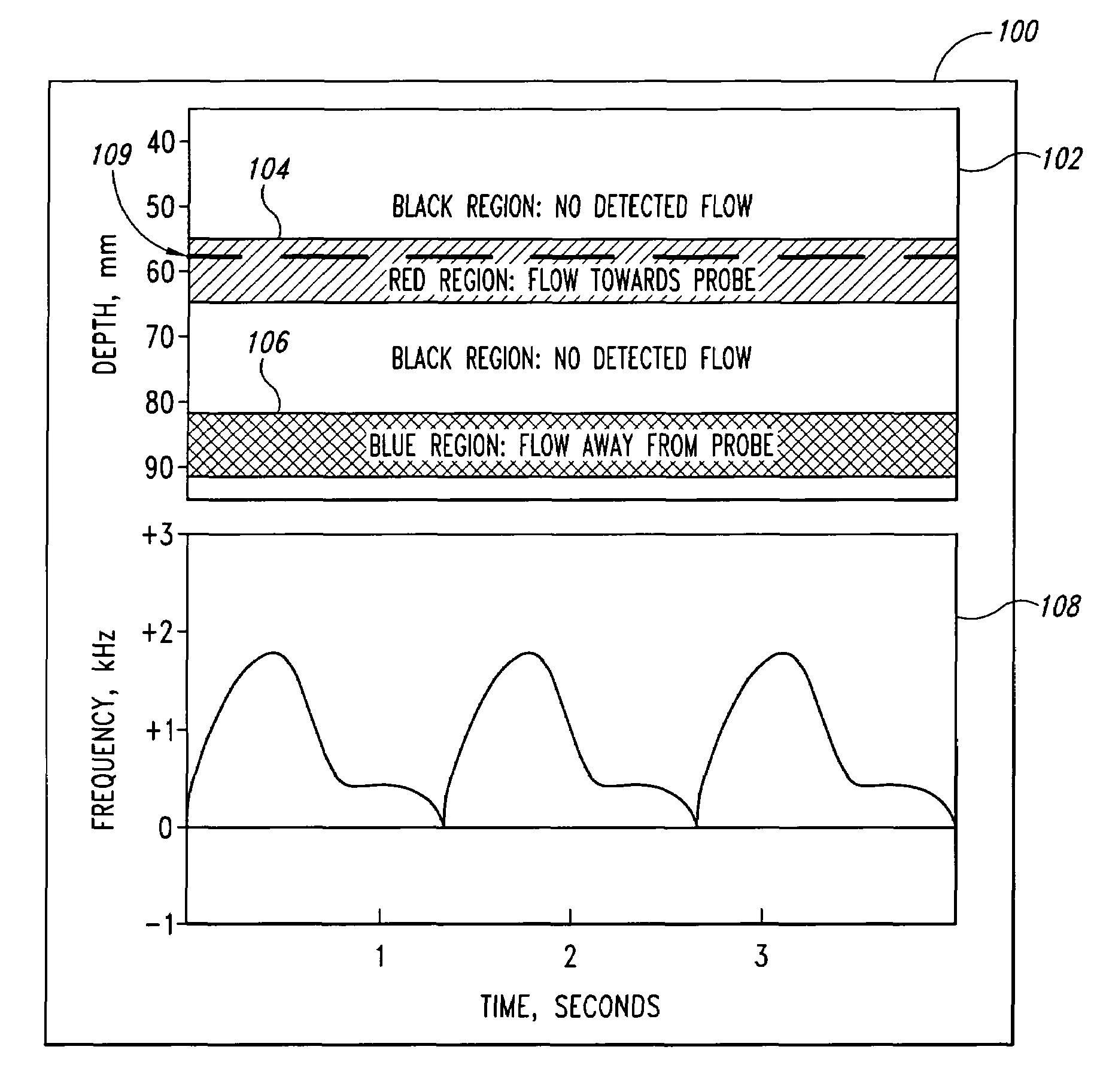
[0025]FIG. 1 is a graphical diagram depicting a first display mode of Doppler ultrasound information in accordance with an embodiment of the invention. In this first display mode, referred to as an Aiming mode 100, two distinct ultrasound displays are provided to the user. A depth-mode display 1...


PUM


Abstract

A pulse Doppler ultrasound system and associated methods are described for monitoring blood flow. A graphical information display includes simultaneously displayed depth-mode and spectrogram displays. The depth-mode display indicates the various positions along the ultrasound beam axis at which blood flow is detected. These positions are indicated as one or more colored regions, with the color indicating direction of blood flow and varying in intensity as a function of detected Doppler ultrasound signal amplitude or detected blood flow velocity. The depth-mode display also includes a pointer whose position may be selected by a user. The spectrogram displayed corresponds to the location identified by the pointer. Embolus detection and characterization are also provided.

Description

CROSS-REFERENCE TO RELATED APPLICATION[0001]This application is a continuation of U.S. patent application Ser. No. 09 / 595,323, filed Jun. 16, 2000, issued Sep. 9, 2003 as U.S. Pat. No. 6,616,611, which is a continuation of U.S. patent application Ser. No. 09 / 190,402, filed Nov. 11, 1998, issued Mar. 6, 2001 as U.S. Pat. No. 6,196,972.STATEMENT AS TO GOVERNMENT RIGHTS[0002]This invention was made with United States Government support under Grant No. 2 R44 HL 57108-02 awarded by National Institutes of Health (NIH). The United States Government has certain rights in the invention.TECHNICAL FIELD[0003]The invention relates generally to medical monitoring and diagnostic procedures and devices, and more particularly to a Doppler ultrasound method and apparatus for monitoring blood flow.BACKGROUND OF THE INVENTION[0004]Doppler ultrasound has been used to measure blood flow velocity for many years. The well-known Doppler shift phenomenon provides that ultrasonic signals reflected from movin...

Claims


Application Information

Patent Timeline
Patent Type & Authority Patents(United States)
IPC IPC(8): A61B8/06G01S7/52G01S15/58G01S15/89
CPCA61B8/06A61B8/463G01S7/52036G01S7/52046G01S7/52071G01S7/52073G01S15/8984G01S15/8988A61B8/0816A61B8/488
Inventor MOEHRING, MARK A.
Owner SPENTECH
Why Eureka
Try Eureka