Image-forming device for absorbing vibration of guide plate

a technology of guide plate and vibration, applied in the direction of instruments, optics, electrographic process apparatus, etc., can solve the problems of generating noise and reducing the quality of images formed on paper, and achieve the effect of suppressing flapping noise and improving the quality of images formed

Active Publication Date: 2009-05-26
BROTHER KOGYO KK
View PDF24 Cites 5 Cited by
  • Summary
  • Abstract
  • Description
  • Claims
  • Application Information

AI Technical Summary

Benefits of technology

[0008]Therefore, it is an object of the present invention to provide an image-forming device and a process cartridge capable of suppressing flapping noise from the guide plate, while improving the quality of images formed on the paper.
[0011]By providing a cushioning member that is disposed at a side of the second surface and formed from a material softer than a material of the guide plate, the cushioning member can absorb vibrations in the guide plate when the trailing edge of the paper leaves the guide plate. Further, the cushioning member protruding farther toward the image-carrying member than the edge of the guide plate on the image-carrying member side is softer than the guide plate to reduce the possibility of damage to the image-carrying member from contact by the cushioning member. As a result, the cushioning member can be extended near the image-carrying member for supporting the trailing edge of the paper in the space between the transfer position and the guide plate, thereby restraining flapping of the trailing edge.
[0012]Since the cushioning member of the present invention can absorb vibrations in the guide plate, the structure of the present invention can suppress flapping noise from the guide plate. Further, since the cushioning member supports the trailing edge of the paper, the cushioning member can restrain flapping of the trailing edge of the paper, thereby improving the quality of images formed on the paper.

Problems solved by technology

However, when the paper is separated from the photosensitive drum at a position upstream of a transfer position between the photosensitive drum and the transfer roller with respect to the paper-conveying direction, a pre-transfer may occur in which an electric field produced between the paper and the photosensitive drum causes developer to scatter from the photosensitive drum onto the paper.
However, when the guide plate is formed of a film or other flexible member in the technology described above, the guide plate bent by the paper returns to its original position and flaps when the trailing edge (upstream end) of the paper leaves the guide plate, potentially generating noise (referred to as “flapping”).
Such flapping in the trailing edge of the paper may cause problems in transferring developer, leading to a drop in quality of the images formed on paper.

Method used


Image

  • Image-forming device for absorbing vibration of guide plate
  • Image-forming device for absorbing vibration of guide plate
  • Image-forming device for absorbing vibration of guide plate

Examples


Embodiment Construction

[0027]Next, a preferred embodiment of the present invention will be described.

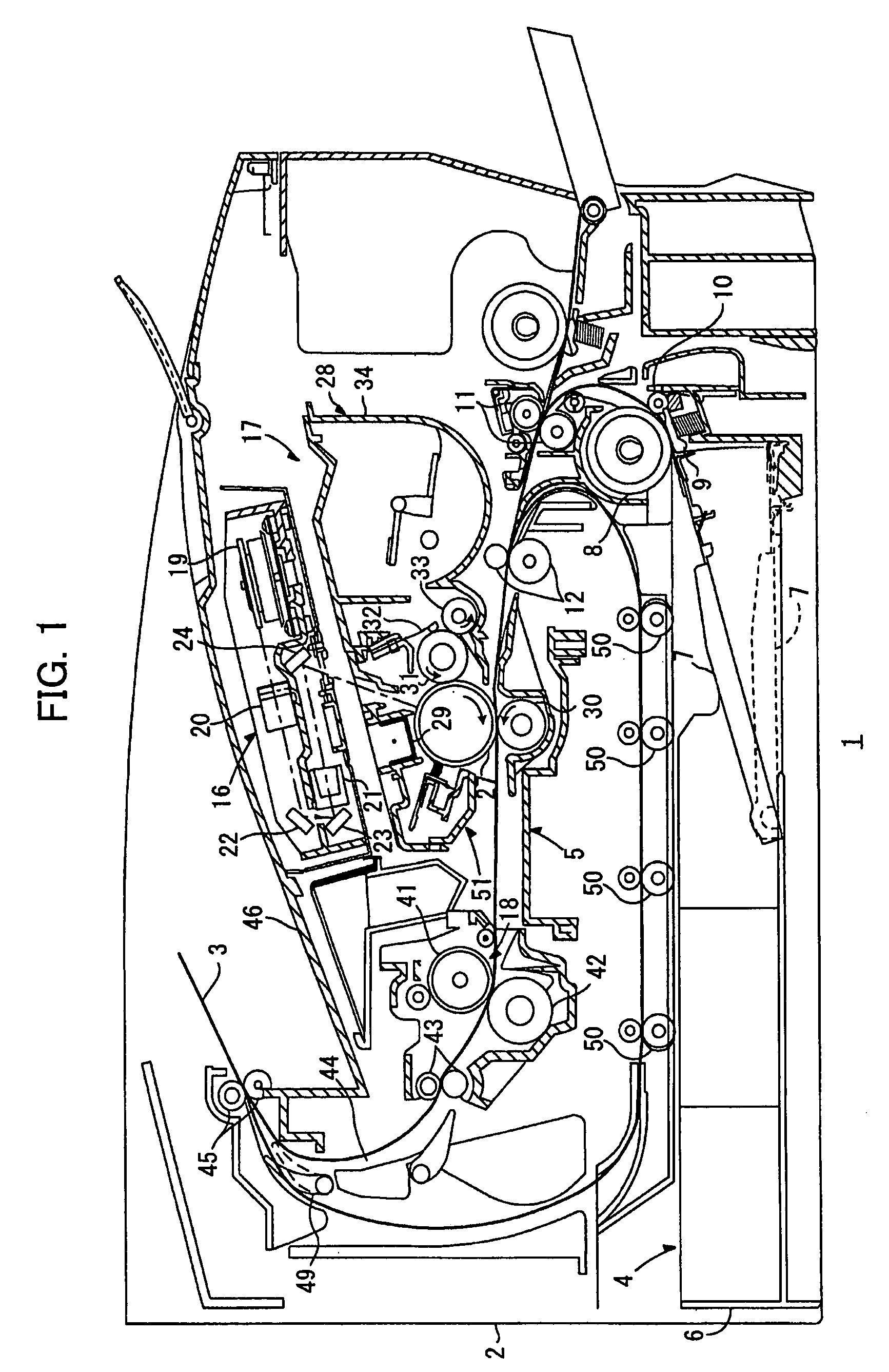
[0028]First, the overall structure of a laser printer will be briefly described as an example of the image-forming device according to the present invention. FIG. 1 is a side cross-sectional view of a laser printer 1 serving as a preferred embodiment of the image-forming device according to the present invention. As shown in FIG. 1, the laser printer 1 includes a main casing 2 and, within the main casing 2, a feeding unit 4 for feeding sheets of a paper 3, and an image-forming unit 5 for forming images on the paper 3 supplied by the feeding unit 4.

[0029]The feeding unit 4 includes a paper tray 6 detachably mounted in the bottom section of the main casing 2, a paper-pressing plate 7 provided inside the paper tray 6, a feeding roller 8 and a feeding pad 9 disposed above one end of the paper tray 6, paper dust rollers 10 and 11 disposed downstream of the feeding roller 8 in the conveying direction of the pape...


PUM


Abstract

An image-forming device includes a photosensitive drum, a transfer roller, a guide plate for guiding the paper toward the photosensitive drum, and a sponge fixed to the bottom surface of the guide plate. The sponge is softer than the guide plate, so that it can absorb vibrations in the guide plate when the trailing edge of the paper leaves the guide plate.

Description

CROSS REFERENCE TO RELATED APPLICATION[0001]This application is a continuation-in-part application of application Ser. No. 11 / 340,539 filed Jan. 27, 2006, claiming priorities from Japanese patent application Nos. 2005-21992 and 2005-21993 both filed Jan. 28, 2005. This application further claims priority from Japanese Patent Application No. 2006-202211 filed Jul. 25, 2006. The entire contents of these priority applications are incorporated herein by reference.BACKGROUND OF THE INVENTION[0002]1. Field of the Invention[0003]The present invention relates to an image-forming device such as a laser printer, and to a process cartridge detachably provided in the image-forming device.[0004]2. Description of the Related Art[0005]Generally, laser printers and other electrophotographic image-forming devices are provided with a photosensitive drum for carrying a developer image, and a transfer roller disposed in contact with the photosensitive drum for attracting the developer image with a tran...

Claims


Application Information

Patent Timeline
Patent Type & Authority Patents(United States)
IPC IPC(8): G03G15/16
CPCG03G15/165
Inventor HATTORI, MAKOTOTOKUDA, HIROSHIDEGUCHI, HIDEAKI
Owner BROTHER KOGYO KK
Why Eureka
Try Eureka