Eureka AIR delivers breakthrough ideas for toughest innovation challenges, trusted by R&D personnel around the world.

Film dispenser with pre-stretch assembly

a film dispenser and pre-stretch technology, which is applied in the direction of bundling articles, bundling machine details, packaging goods types, etc., can solve the problems of time-consuming and difficult process of threading film web through the pre-stretch portion of the film dispenser, and the difficulty of threading operation and time-consuming

Active Publication Date: 2009-06-02
LANTECH COM
View PDF12 Cites 49 Cited by
  • Summary
  • Abstract
  • Description
  • Claims
  • Application Information

AI Technical Summary

Problems solved by technology

However, the procedure of threading the film web through the series of rollers in the film web dispenser prior to operation of the stretch wrapping apparatus has been found to be time consuming and difficult.
The increased numbers of rollers in the film dispensers for pre-stretch and the close spacing of such rollers with their effective interconnection for pre-stretching the film web prior to dispensing the film web on the load makes it very difficult to thread the film web through the pre-stretch portion of the film dispenser.
This threading operation is difficult and time consuming since, due to the close spacing of the rollers, an operator cannot manually carry the stretch wrap packaging material between the rollers.
This procedure is rendered considerably more difficult because of the large widths of the stretch wrap packaging material which are used commercially.
Other problems in threading resulted from the fact that the operator was required to place his fingers proximate to the nip of the rollers and blindly feed the film from the rear of the frame which carried the rollers, which made the threading operation difficult and more time consuming.
The roll carriage utilized two pre-stretch rollers cantilevered and supported only at the top of the roll carriage, such that the bottoms of the rollers were unsupported and unconnected to any structure.
This design was unsuccessful due to very significant problems in dealing with the forces exerted on the unsupported rollers.
The forces caused deformation of the rollers and the mis-alignment of the gears used to maintain relative speeds of the two pre-stretch rollers.

Method used


Image

  • Film dispenser with pre-stretch assembly
  • Film dispenser with pre-stretch assembly
  • Film dispenser with pre-stretch assembly

Examples


Embodiment Construction

[0040]Reference will now be made in detail to the present exemplary embodiment of the invention, an example of which is illustrated in the accompanying drawings. Wherever possible, the same reference numbers will be used throughout the drawings to refer to the same or like parts.

[0041]In accordance with the present invention, an apparatus is provided for wrapping a load with packaging material. The apparatus includes a packaging material dispenser having a cantilevered pre-stretch assembly configured to pre-stretch the packaging material, and means for providing relative rotation between the load and the dispenser to wrap packaging material around the load.

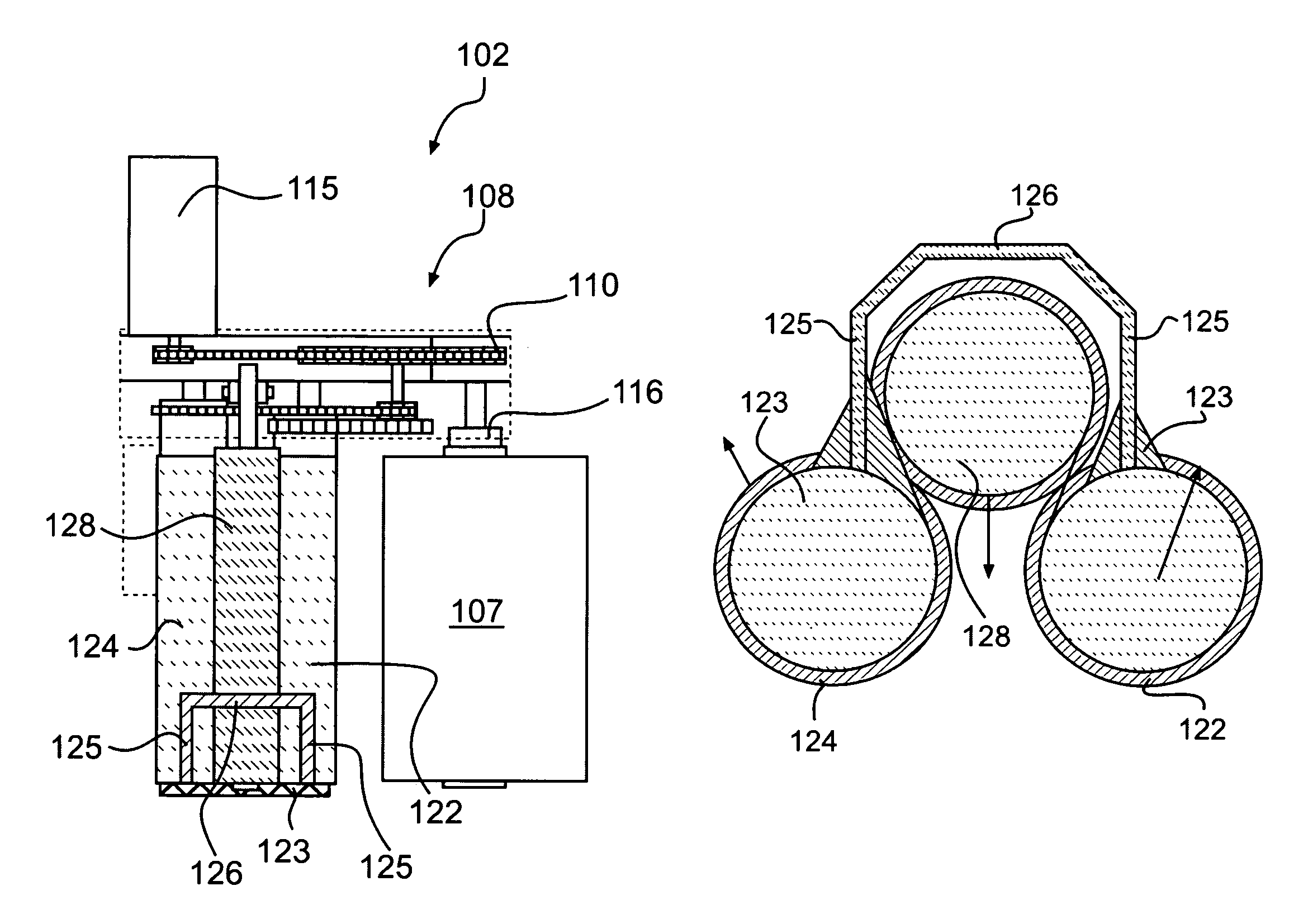
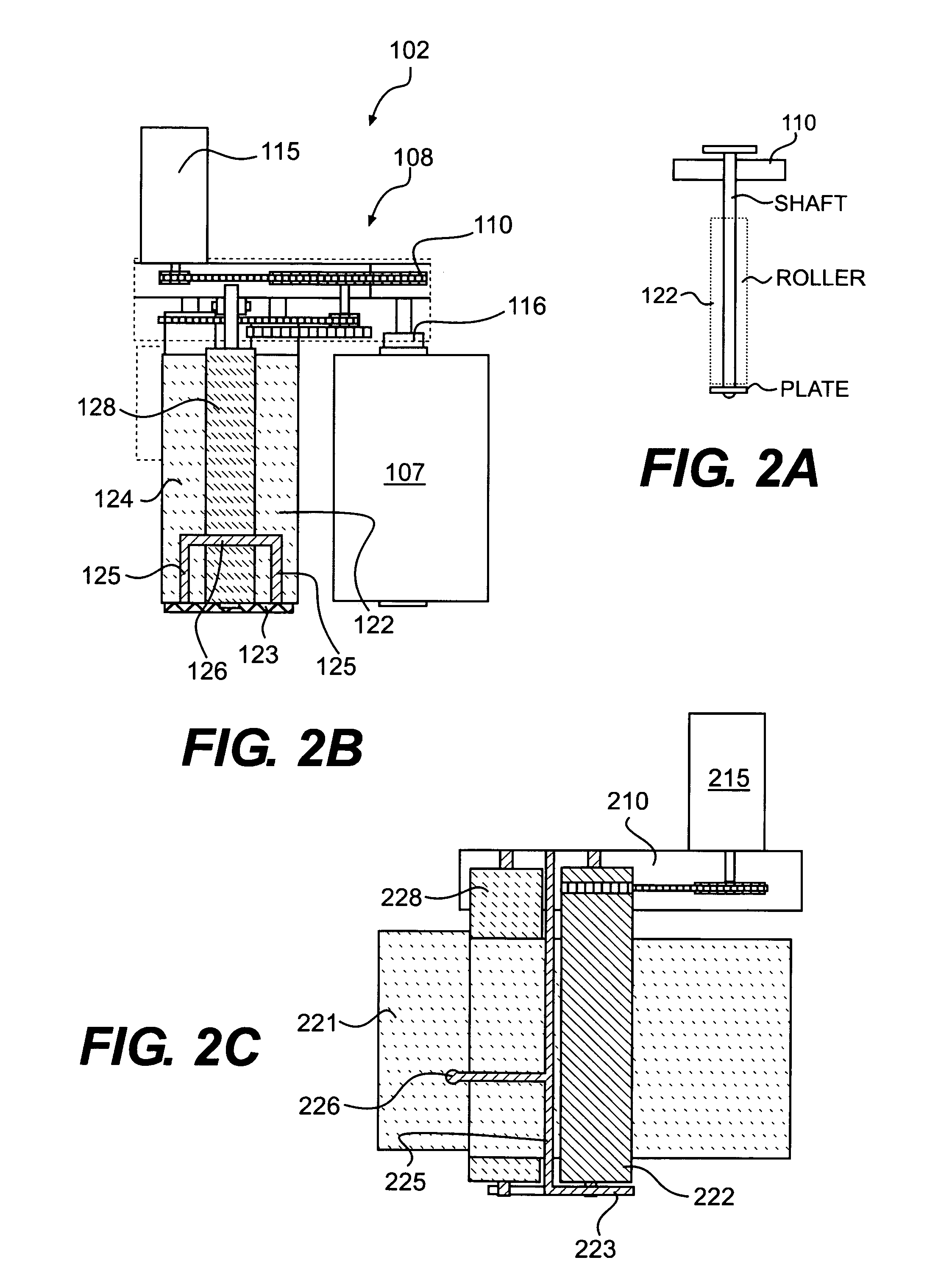
[0042]As embodied herein and shown in FIGS. 2B, 2C, 5, 6, and 11, an apparatus 100 includes a packaging material dispenser 102. As shown in FIG. 11, packaging material dispenser 102 dispenses a sheet of packaging material 111 in a web form. As shown in FIGS. 2B, 2C, and 5, packaging material dispenser 102 has a roll carriage frame...


PUM

PropertyMeasurementUnit
widthaaaaaaaaaa
outer diameteraaaaaaaaaa
lengthaaaaaaaaaa

Abstract

A film dispenser for a stretch wrapping apparatus is provided. The film dispenser includes a pre-stretch assembly having a top portion mounted to and extending downwardly from a drive plate of a roll carriage frame. The pre-stretch assembly includes two pre-stretch rollers having first ends connected to the roll carriage frame and second ends connected to one another. The pre-stretch rollers may be coated. The pre-stretch assembly further includes a cantilevered idle roller mounted to the drive plate and positioned between the pre-stretch rollers. A film path is defined by the space between the pre-stretch rollers and the idle roller. The film path is easily accessible via the bottom end of the pre-stretch assembly.

Description

[0001]This application claims priority under 35 U.S.C. § 119 based on U.S. Provisional Application No. 60 / 659,886, filed Mar. 10, 2005, the complete disclosure of which is incorporated herein by reference.FIELD OF THE INVENTION[0002]The present invention relates to stretching wrapping apparatus having a film dispenser with a cantilevered pre-stretch assembly.BACKGROUND OF THE INVENTION[0003]Various packaging techniques have been used to build a load of unit products and subsequently wrap them for transportation, storage, containment and stabilization, protection and waterproofing. Products may be stacked as a load on a pallet to simplify handling of the products. The load is commonly wrapped with stretch wrap packaging material. One system uses stretch wrapping machines to stretch, dispense and wrap stretch packaging material around a load. Stretch wrapping can be performed as an inline, automated packaging technique that dispenses and wraps packaging material in a stretch condition...

Claims


Application Information

Patent Timeline
Patent Type & Authority Patents(United States)
IPC IPC(8): B65B53/00
CPCB29C55/06B65B11/025B65B11/045B65B11/585B65H23/10B65H23/188B65B2011/002B65B2210/16
Inventor LANCASTER, III, PATRICK R.JOHNSON, RICHARD L.HALL, WILLIE MARTINANDERSON, JEREMY D.ELDRIDGE, DAVID
Owner LANTECH COM
Why Eureka
Eureka Blog
Learn More