Master cylinder lever for a hydraulic brake with dead-band adjustment mechanism

a technology of hydraulic brakes and master cylinders, applied in the direction of fluid couplings, cycle equipments, cycle brakes, etc., can solve the problems of difficult operation and complex structur

Inactive Publication Date: 2009-06-02
SHIMANO INC
View PDF9 Cites 30 Cited by
  • Summary
  • Abstract
  • Description
  • Claims
  • Application Information

AI Technical Summary

Benefits of technology

[0009]In a preferred embodiment, the adjustment guide body comprises a first opening adjacent the second end that has an axle pin extending therethrough. The axle pin engages an inside surface of the housing, thereby providing for pivotable movement of the adjustment guide body.

Problems solved by technology

These structure are very complex and difficult to operate.

Method used


Image

  • Master cylinder lever for a hydraulic brake with dead-band adjustment mechanism
  • Master cylinder lever for a hydraulic brake with dead-band adjustment mechanism
  • Master cylinder lever for a hydraulic brake with dead-band adjustment mechanism

Examples


Embodiment Construction

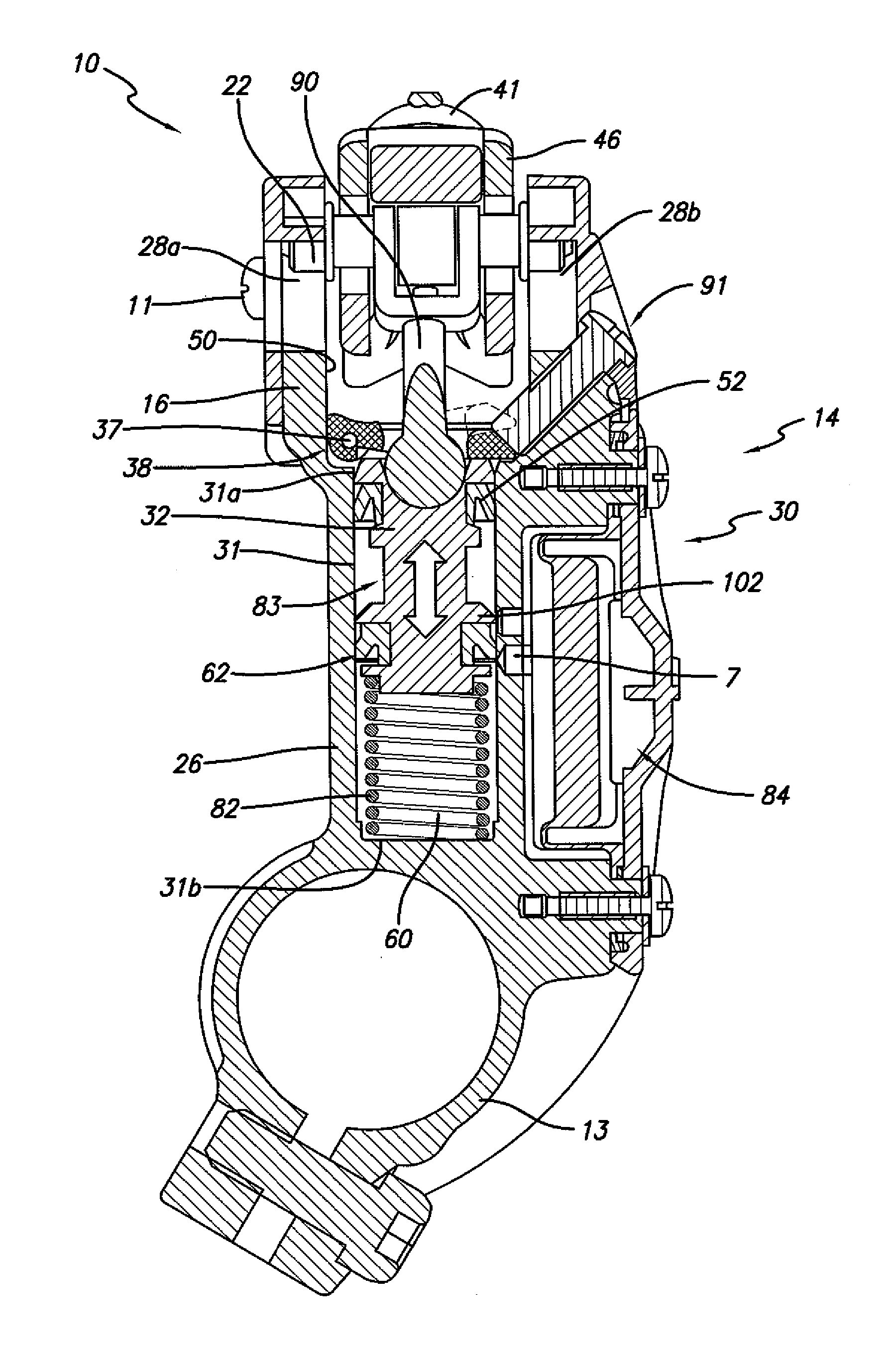
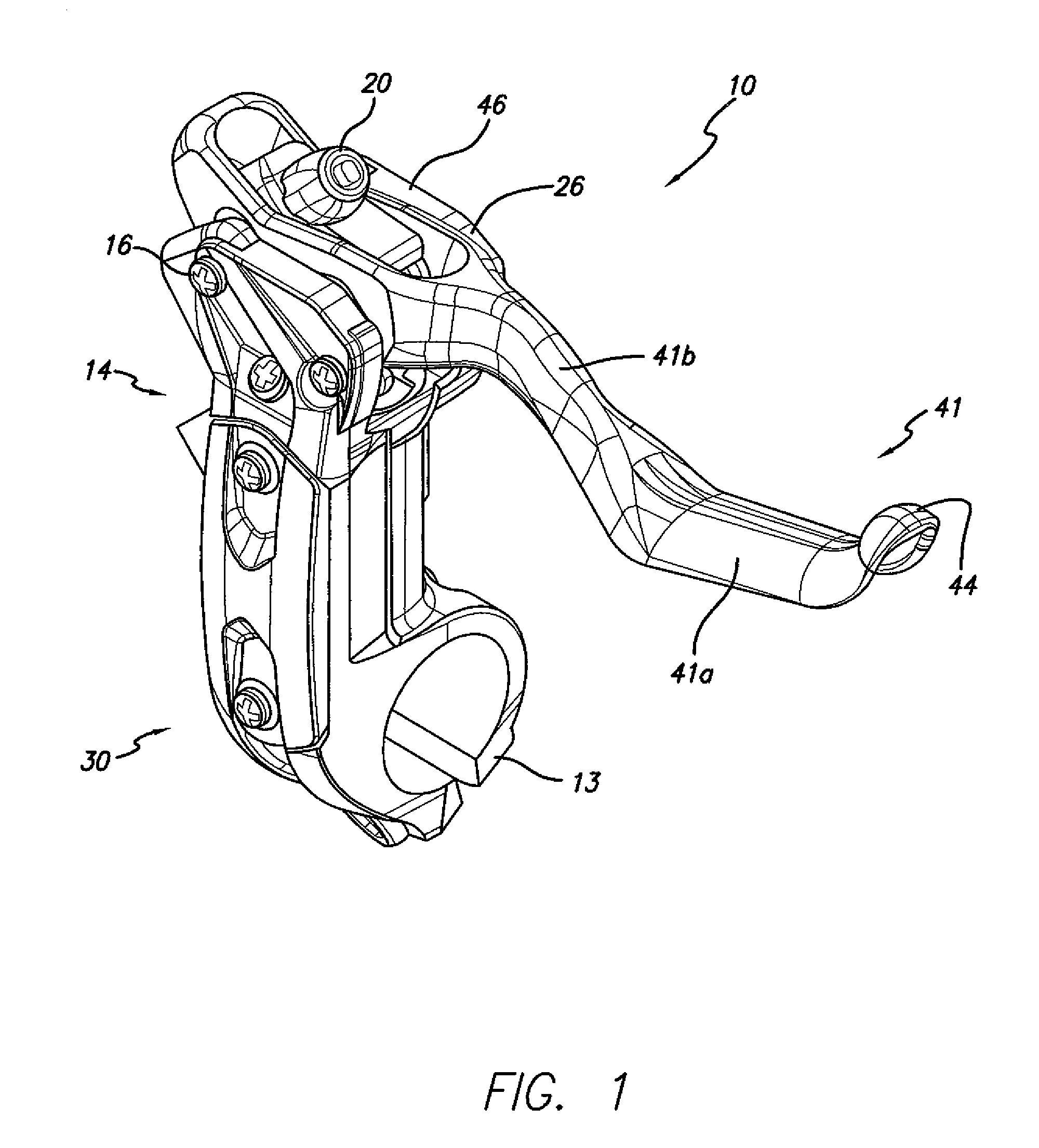
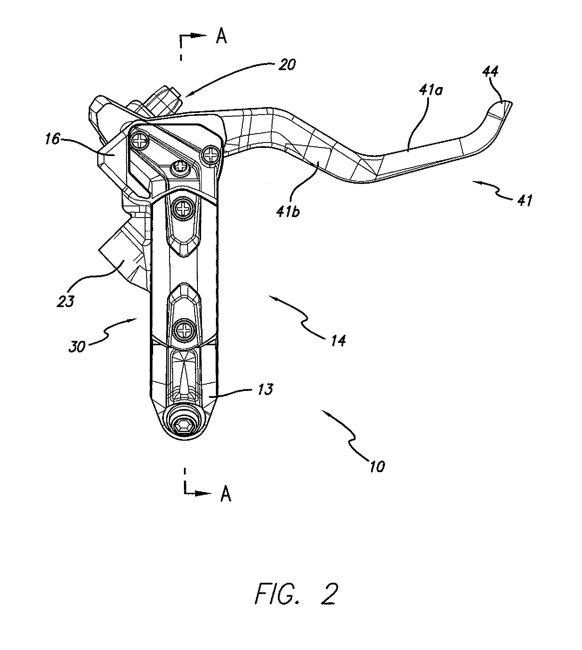
[0004]According to one aspect of the present invention, there is provided a preferred embodiment of the present invention, a master cylinder assembly for a bicycle hydraulic disc brake is provided. The master cylinder assembly comprises a housing defining a cylinder having a first end and a second end, a hydraulic fluid reservoir, and a port providing fluid communication between the cylinder and the hydraulic reservoir. A piston having a radial seal is received in the cylinder, wherein the piston is moveable between a select starting position with the seal between the first end of the cylinder and the port and a pressurized position with the seal between the port and the second end of the cylinder. A lever is pivotably attached to the housing, the lever being operatively associated with the piston to move the piston between the select starting position and the pressurized position as the lever is pivoted between a rest position and a fully-actuated position. An adjustment guide body...


PUM


Abstract

A master cylinder assembly for a bicycle disc brake having a housing defining a cylinder, a piston received in the cylinder, a lever pivotably attached to the housing, and an adjustment guide body that is operatively associated with the piston. The piston is moveable within the cylinder between a select starting position and a pressurized position. The lever is operatively associated with the piston to move the piston from the select starting position to the pressurized position as the lever is pivoted between a rest position and a fully-actuated position. The adjustment guide body is pivotable between a first position and a second position for adjusting the select starting position of the piston.

Description

FIELD OF THE INVENTION[0001]The present invention relates to master cylinder levers for hydraulic brakes, and more particularly, to a master cylinder lever having an adjustment mechanism for adjusting the starting position of the piston.BACKGROUND OF THE INVENTION[0002]Many hydraulic brake master cylinders operate in the same basic way. They typically include a master piston in a master cylinder which is actuated by a brake lever. A piston is moveable within the cylinder from a start position near a first end of the cylinder to a pressurized position near the second end of the cylinder. Between the first and second ends of the cylinder is a port in fluid communication between an inside of the cylinder and a hydraulic fluid reservoir. As the piston moves from the start position toward the port, hydraulic fluid flows from the port to the reservoir. Once the seal associated with the piston moves between the port and the second end of the cylinder, fluid within the second end of the cyl...

Claims


Application Information

Patent Timeline
Patent Type & Authority Patents(United States)
IPC IPC(8): B60T11/22B62L3/00
CPCB60T7/10B60T11/18B62L3/023
Inventor TAKIZAWA, SHINICHIWATARAI, ETSUYOSHI
Owner SHIMANO INC
Why Eureka
Try Eureka