Three-way poppet valve for work exchanger

a technology of poppet valve and work exchanger, which is applied in the direction of multiple way valve, reverse osmosis, mechanical equipment, etc., can solve the problems of internal and external leakage problems, and the rotary valve of the tonner is not hydraulically balanced, so as to reduce the use of expensive materials, and ensure the sealing effect of the por

Inactive Publication Date: 2009-06-02
IDE TECHNOLOGIES
View PDF16 Cites 9 Cited by
  • Summary
  • Abstract
  • Description
  • Claims
  • Application Information

AI Technical Summary

Benefits of technology

[0014]In one embodiment of the three-way valve, the first valve seat is at a distal end of the first cylindrical passage, adjacent the first port, and a distal end of the first cylinder part of the poppet is equipped with a first sealing rim matching the first valve seat. Preferably, the first cylindrical passage has a proximal part flaring towards the poppet body so that the first cylinder part of the poppet body would smoothly change the flow through the first port and the pressure in the valve chamber when entering or exiting the first cylinder passage.
[0015]The second valve seat is at a proximal end of the second cylindrical passage, adjacent the valve chamber, and a proximal end of the second cylinder part of the poppet is equipped with a second sealing rim matching the second valve seat. Preferably, said poppet body further comprises a profiled part adjacent to the distal end of the second cylinder part, so that the profiled part would smoothly change the flow through the second port and the pressure in the valve chamber when entering or exiting the second cylinder passage.
[0022]The poppet valve of the present invention provides combined advantages of poppet and spool valves: reliable sealing of the ports, avoiding mixing of flows and leakages, controlled shut-off and opening of the flow passages and preventing water-hammer, axially balanced poppet assembly allowing low-power drives, reduced use of expensive materials, robust construction and low production costs.
[0023]The three-way poppet valve of the present invention is advantageously used in energy recovery plants of RO installations of large capacity. It allows constructing of large work exchanger units where a number of exchanger cylinders are connected in parallel to one poppet valve. Opposite-phase operation of two work exchangers, which is necessary in such energy recovery plant, can be effectively synchronized by designing the profile of the poppets such that while one valve opens its high-pressure brine port and the other valve closes its high-pressure brine port, the total sectional area of the high-pressure brine flow remains constant.
[0024]The three-way poppet valve of the present invention, with the hydraulic drive, can be advantageously used also at the feed water end of the work exchangers, instead of two check valves. Thus, with no springs or other elastic elements used in valve motion, arbitrary closing / opening or “hesitation” of the valves is avoided, as well as noise and “water hammer”.

Problems solved by technology

The rotary valve of Tonner is not hydraulically balanced, which causes excessive wear on the sealing surfaces due to side loads exerted on the central rotating assembly.
There are also internal and external leakage problems between the high pressure inlet and outlet ports and the low pressure drain ports.
This, in turn, reduces the efficiency of the Tonner valve and imposes size limits on any such device that can be manufactured in practice.
As a result, the force required to move the linear spool is only that force needed to overcome the friction of the sealing surfaces associated with the pistons, which permits the driving device of the valve to be of low power.
However, the Shumway valve has also leakage problems.
The attempts to reduce leakage by tighter fitting of the pistons to the cylinder lead to excessive wear which seems to be an inherent problem in every spool valve device because the sealing in spool valves is not provided by positive displacement.
The poppet valve also shuts-off and opens abruptly which may cause water hammer, and is not hydraulically balanced.

Method used


Image

  • Three-way poppet valve for work exchanger
  • Three-way poppet valve for work exchanger
  • Three-way poppet valve for work exchanger

Examples


Embodiment Construction

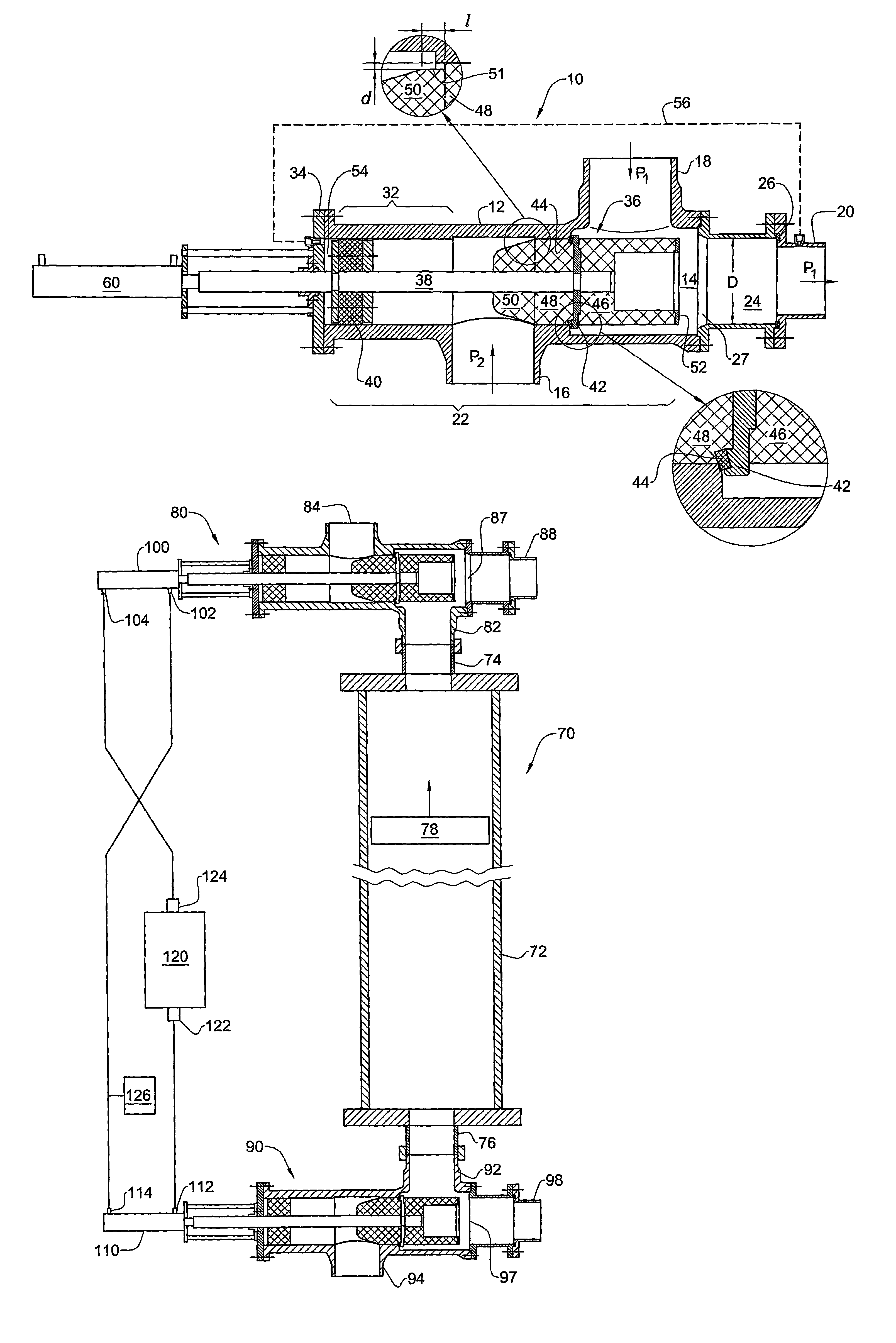
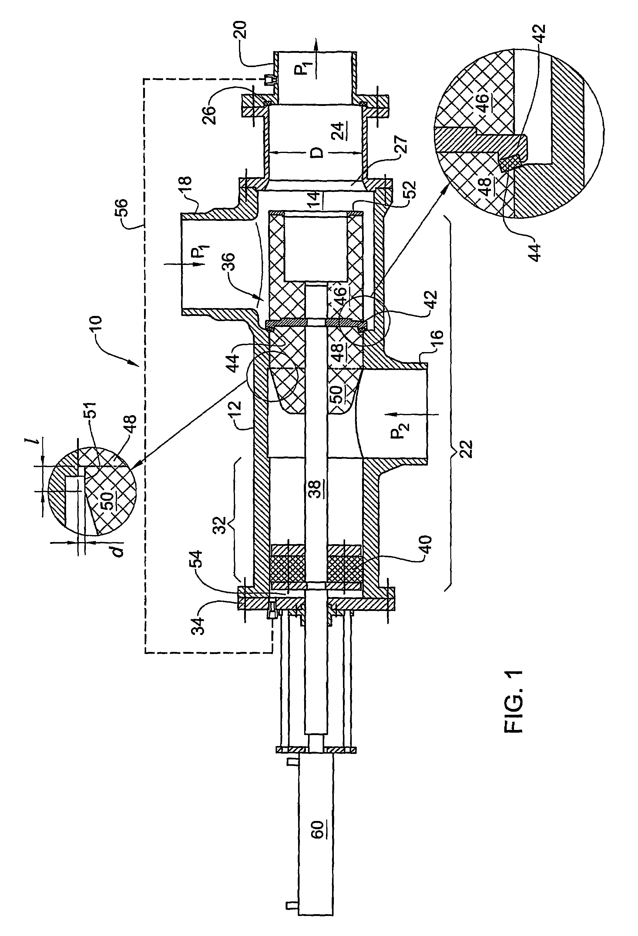
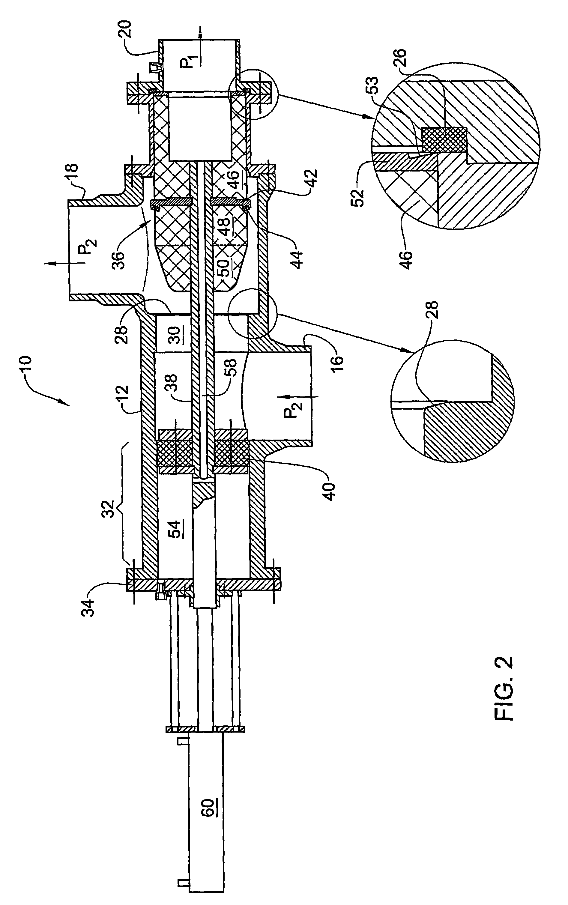
[0031]With reference to FIGS. 1 and 2, there is shown a three-way, two-position poppet valve 10 comprising a housing 12 with a generally cylindrical valve chamber 14, a first (outlet) port 20, a second (inlet) port 16, a third (working) port 18, and a poppet assembly 22. The valve chamber 14 has a coaxial cylinder passage 24 of diameter D towards the inlet port 16. The cylindrical passage 24 comprises a first valve seat 26 of diameter D disposed at the distal end thereof, in communication with the axial outlet port 20, and a flaring annular part 27 at the proximal end. A second annular valve seat 28 is at the opposite side of the valve chamber 14, communicating with the inlet port 16. The working port 18, which is disposed laterally between the valve seats 26 and 28, is directly communicating with the valve chamber 14. A coaxial cylinder passage 30 of diameter D is provided between the valve seat 28 and the inlet port 16. The housing 12 further has an auxiliary coaxial cylinder cham...


PUM


Abstract

A three-way two-position poppet valve (10) comprising a housing (12) with a generally cylindrical valve chamber (14), a first (20) and a second (16) port with coaxial 1 valve seats (26, 28) at the ends of the chamber, and a third lateral working port (18). A poppet body (36) is disposed reciprocably in the valve chamber so that in a first position of the poppet body the first valve seat (26) is sealed and the second port communicates with the working port, and in a second position the second valve seat (28) is sealed and the first port communicates with the working port. The valve is characterized in that the housing has two coaxial cylindrical passages (24, 30) adjacent the respective valve seats, while the poppet body has two coaxial cylinder parts (44, 48) slidingly and sealingly fitting the cylindrical passages, so that the poppet body is always supported in at least one of the cylindrical passages and fluid communication between the first and the second port is always prevented.

Description

FIELD OF THE INVENTION[0001]This invention relates to three-way poppet valves, more particularly to valves specially designed for use in work exchanger systems.BACKGROUND OF THE INVENTION[0002]A work exchanger is a device that obtains energy from one stream of fluid and transfers that energy to another stream. It can be also described as a pump driven by fluid flow, most often of opposed piston / diaphragm type. Work exchangers are vital for energy recovery in reverse osmosis processes such as desalination, since by itself the RO separation is power-consuming process which becomes economically feasible if only a substantial part of the energy resident in the reject or / and permeate streams is returned back into the process.[0003]A work exchanger system typically comprises two (or more) pressure cylinder vessels with a brine port at one end, a feed water port at the other end, and a plunger freely sliding between the ports. A system of valves connects and disconnects these ports to high...

Claims


Application Information

Patent Timeline
Patent Type & Authority Patents(United States)
IPC IPC(8): F15B13/042F16K11/044B01D61/06B01D61/10F04B7/02F04B9/117
CPCB01D61/06B01D61/10F04B7/0225F04B9/1176F16K11/044F16K11/07Y10T137/8663Y10T137/86694
Inventor ROJANSKIY, HENRIKHOPHIR, AVRAHAM
Owner IDE TECHNOLOGIES
Why Eureka
Try Eureka