Chain wear monitoring device

a wear monitoring and chain technology, applied in the direction of machine parts testing, structural/machine measurement, instruments, etc., can solve the problems of wear on both the pins and the center links and/or side links, change in the pitch of the chain, increase in the effective length of the chain or section of the chain,

Inactive Publication Date: 2009-06-02
FROST TECH
View PDF25 Cites 78 Cited by
  • Summary
  • Abstract
  • Description
  • Claims
  • Application Information

AI Technical Summary

Benefits of technology

[0006]The present invention provides a conveyor system that measures the pitch of a chain by directly measuring pin-to-pin distance of adjacent pins of the chain (such as pins at opposite ends of a common center link or a pair of side links). The measurement device utilizes two sensing devices, such as laser sensing devices or the like. One sensing device is operable to sense the presence of a chain portion, such as a pin or other portion of the chain, at a predetermined location and is operable to generate an output signal that triggers or actuates the other sensing device to cause the other sensing device to measure the distance to or to determine the location of the next or subsequent chain portion or pin or the like.

Problems solved by technology

As a section of chain bends, the pins may rotate within the openings in the center links and / or side links, which results in wear on both the pins and the center links and / or side links.
The wear leads to an increase in the effective length of the chain or section of chain as well as a change in the pitch of the chain as gaps then may occur between the pins and links.
It is generally undesirable to allow excessive wear in the chain, since this results in slack in the chain and / or a change in chain pitch and / or a change in the distance between products being processed, or may further result in noise and further wear or weakening of the chain.
However, the center links are typically forged members and may have variable lengths due to the manufacturing tolerances of the center links and surface irregularities of the links.
Such chain characteristics and speed variations may result in a high variability in the measured length of the chain links or sections of chain.

Method used


Image

  • Chain wear monitoring device
  • Chain wear monitoring device
  • Chain wear monitoring device

Examples


Embodiment Construction

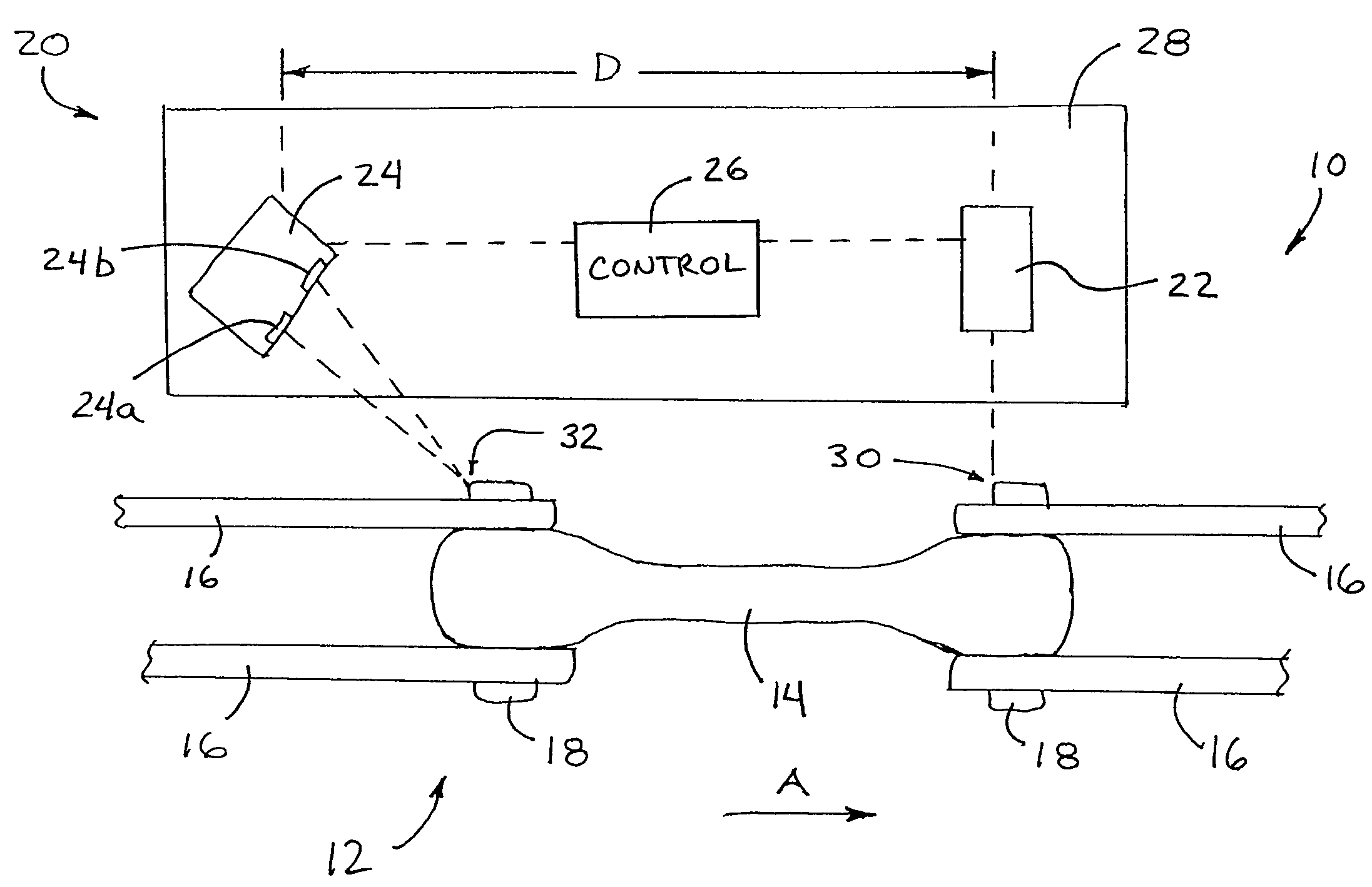
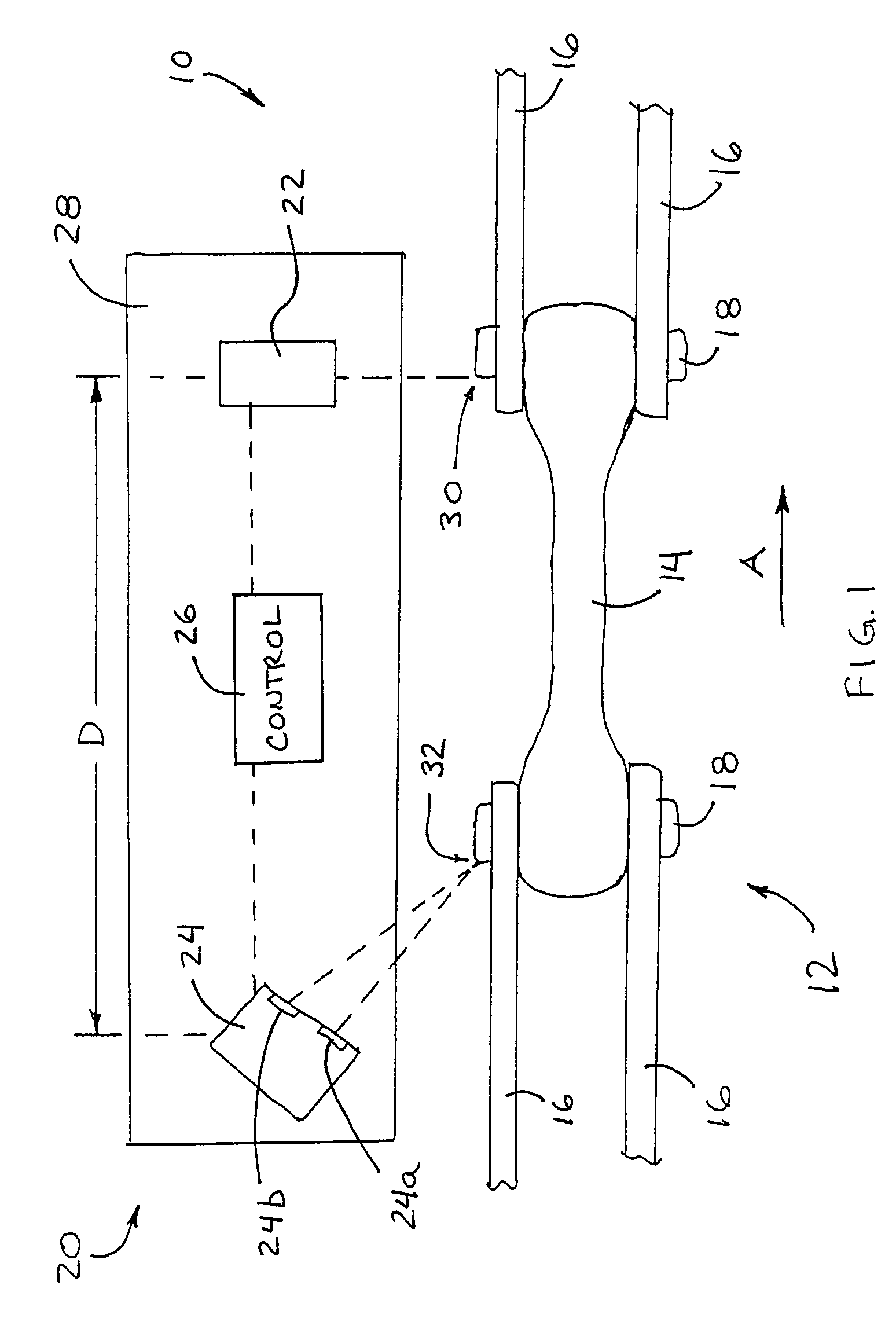
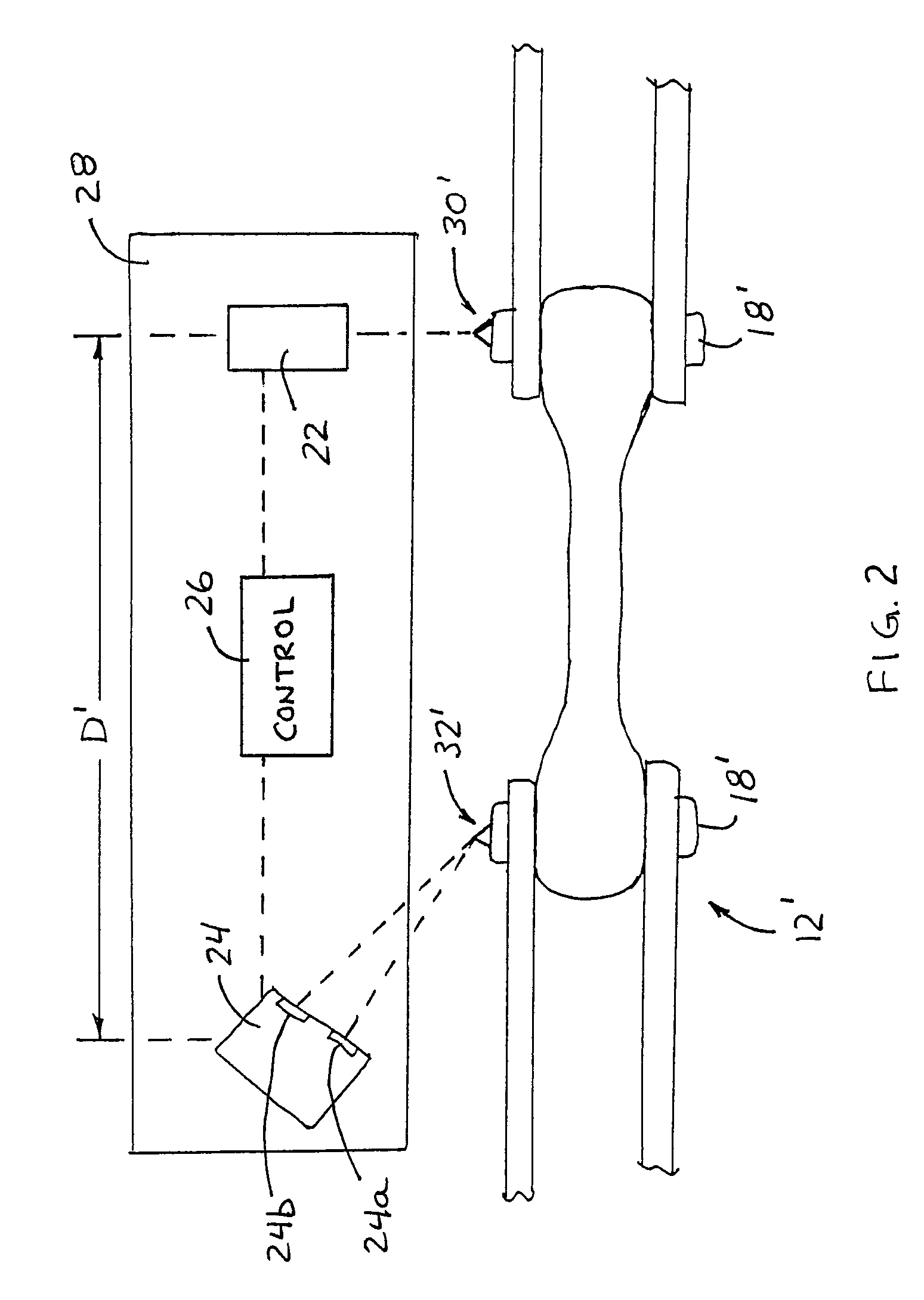
[0023]Referring now to the drawings and the illustrative embodiments depicted therein, a conveyor system 10 includes a conveyor chain 12 routed and driven along a conveying path at or in a facility, such as a warehouse, assembly plant and / or the like (FIG. 1). The conveyor line includes a continuous loop or path or track set up in a desired route or layout, and along which a plurality of trolleys or the like are conveyed. The trolleys are connected together via a continuous drive chain, such as a chain comprising a plurality of chain links (such as center links 14 and side links 16) connected together by a plurality of chain pins 18 (such as I-pins or bolted pins or the like). The conveyor system includes a wear measurement or pitch measurement device or system 20, which includes a first sensor or detecting or sensing device 22 and a second sensor or detecting or sensing device 24. The wear measurement device 20 is located along the conveyor path and with the sensing devices 22, 24 ...


PUM


Abstract

A conveyor system and method of measuring chain wear includes first and second sensing devices positioned at a conveyor line or path and directed toward a conveyor chain that is movable along the conveyor path. The first sensing device senses the presence of a first chain portion of the conveyor chain at a predetermined location as the conveyor chain moves along the conveyor line. The second sensing device senses a second chain portion of the conveyor chain as the conveyor chain moves along the conveyor line. The second sensing device is operable to sense a location of or distance to the second chain portion or may capture an image of the second portion. A controller is operable to determine a degree of wear of a section of chain extending between the first and second chain portions in response to the second sensing device.

Description

CROSS REFERENCE TO RELATED APPLICATION[0001]The present application claims the benefit of U.S. provisional application, Ser. No. 60 / 839,980, filed Aug. 24, 2006, which is hereby incorporated herein by reference in its entirety.FIELD OF THE INVENTION[0002]The present invention relates generally to conveying systems and, more particularly, to conveying systems and chains for conveying materials around a conveying path or track of a facility, such as a warehouse or an assembly plant or processing plant or the like.BACKGROUND OF THE INVENTION[0003]Chains for power transmission or for material handling and processing systems, such as, for example, chains which function to move a plurality of trolleys or the like along a path or conveyor line in a processing plant, warehouse or the like, typically include multiple sections or links joined together by pins or bolts, such as I-pins or other connecting elements. As the chain is moved along the conveying path, the links and sections of the ch...

Claims


Application Information

Patent Timeline
Patent Type & Authority Patents(United States)
IPC IPC(8): B65G43/00G01M99/00
CPCB65G43/02G01M13/023G01B11/043B65G2203/0266B65G2203/042B65G2207/48
Inventor RATHBUN, JONATHAN M.MELTON, JR., JOSEPH S.
Owner FROST TECH
Why Eureka
Try Eureka