Electrical connector

Inactive Publication Date: 2009-06-02
TYCO ELECTRONICS AMP ITAL +1
View PDF13 Cites 22 Cited by
  • Summary
  • Abstract
  • Description
  • Claims
  • Application Information

AI Technical Summary

Benefits of technology

[0006]It is an object of the present invention to provide an electrical connector and an electrical connector arrangement which require little space and are simply in construction and robust in their later application. It is a further objec

Problems solved by technology

The AC-voltage and the alternating current component, in particular, on transmission of power between the power converter and the motors, lead to the emission of electromagnetic interference signals which disturb other electrical and electronic systems inside and outside the vehicle.
For this reason, the electrical connectors which have been used in the power tran

Method used


Image

  • Electrical connector
  • Electrical connector
  • Electrical connector

Examples


Embodiment Construction

)

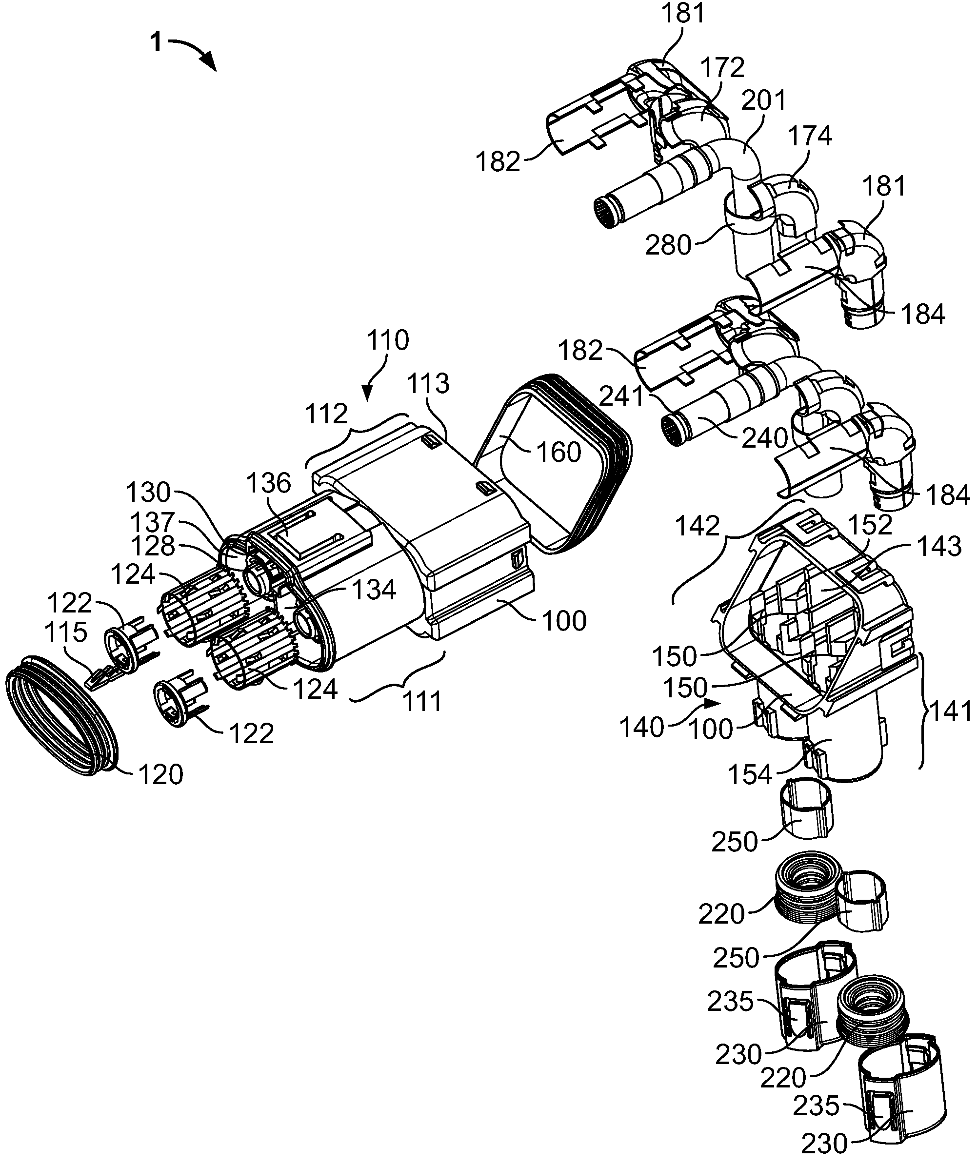
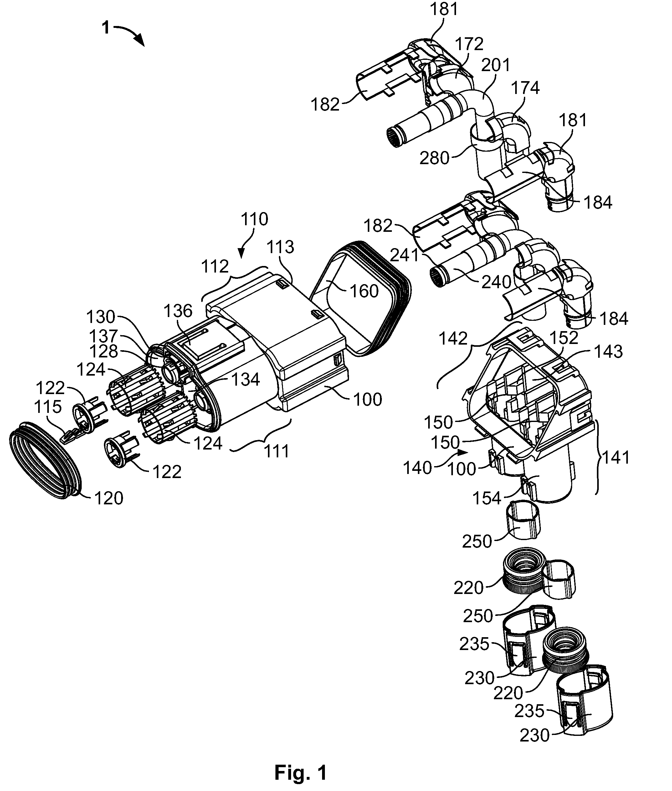
[0014]In this discussion, an electrical connector is an electrical component which is intended to both be firmly or permanently connected to an electrical cable and to form a connection with a mating component (possibly a detachable plug-and-socket type connection). Hereinafter, the mating component of the electrical connector is referred to as a connector receptacle. The electrical connector is a separate component, which serves to connect the cable with the connector receptacle. The connector receptacle and electrical connector may be incorporated into a housing of any desired apparatus.

[0015]Referring now to FIG. 1 in the drawings, an electrical connector 1 according to the invention. The electrical connector 1 comprises a housing 100 comprising two parts, a body 110 and a cable raceway 140. The present invention provides the advantage of a small high-current electrical connector 1 for a vehicle, in part, due to its angled configuration. It is possible to electrically connect a ...


PUM


Abstract

An electrical connector having a housing having a body and a plug tip, a cable raceway having a raceway riser configured to receive a cable, the cable raceway being configured for attachment to the body, wherein the plug tip of the housing is angled with respect to a raceway riser when the cable raceway is attached to the body is disclosed.

Description

CROSS-REFERENCE TO RELATED APPLICATIONS[0001]This application claims the benefit of the filing date under 35 U.S.C. §119(a)-(d) of foreign patent application EP 06 425 543.3 of Jul. 28, 2006.FIELD OF THE INVENTION[0002]The present invention relates to an electrical connector for an electrical cable, in particular to an angled electrical connector, for transmitting high voltages and high currents to or from a receptacle for the electrical connector, particularly in a motor vehicle.BACKGROUND[0003]In engineering, particularly in electrical engineering, a large number of electrical connectors and connector receptacles of many different types are known. These serve to transmit electrical power and / or electrical signals with the widest possible range of voltages, currents, frequencies, and data rates. Furthermore, electrical connector and connector receptacle fulfill other functions. For damp, dusty, or chemically aggressive environments, electrical connectors and connector receptacles c...

Claims


Application Information

Patent Timeline
IPC IPC(8): H01R13/64H01M50/50H01R13/646H01R13/658
CPCB60L11/1818H01R13/6592H01R13/506H01R13/533H01R24/545H01M2/20H01M8/02H01M8/2465H01M2250/20H01R13/5202H01R13/5205H01R13/5219H01R13/65802H01R2105/00H01R2201/26Y02T10/7005Y02T90/14Y02T90/32Y02T10/7072H01R13/6583B60L53/16Y02T90/40Y02T10/70Y02E60/50Y02E60/10H01M50/50
Inventor SARDI, MARCOPLAZIO, ADRIANOAMERIO, FULVIOECKEL, MARKUSBAHR, MARKUSWOLLER, JOSEFMAIER, WOLFGANG
Owner TYCO ELECTRONICS AMP ITAL
Why Eureka
Try Eureka