
Memory module having on-package or on-module termination

a memory module and module technology, applied in the field of memory modules, to achieve the effect of reducing noise and signal reflection

Active Publication Date: 2009-06-02
KIOXIA CORP
View PDF10 Cites 9 Cited by
  • Summary
  • Abstract
  • Description
  • Claims
  • Application Information

AI Technical Summary

Benefits of technology

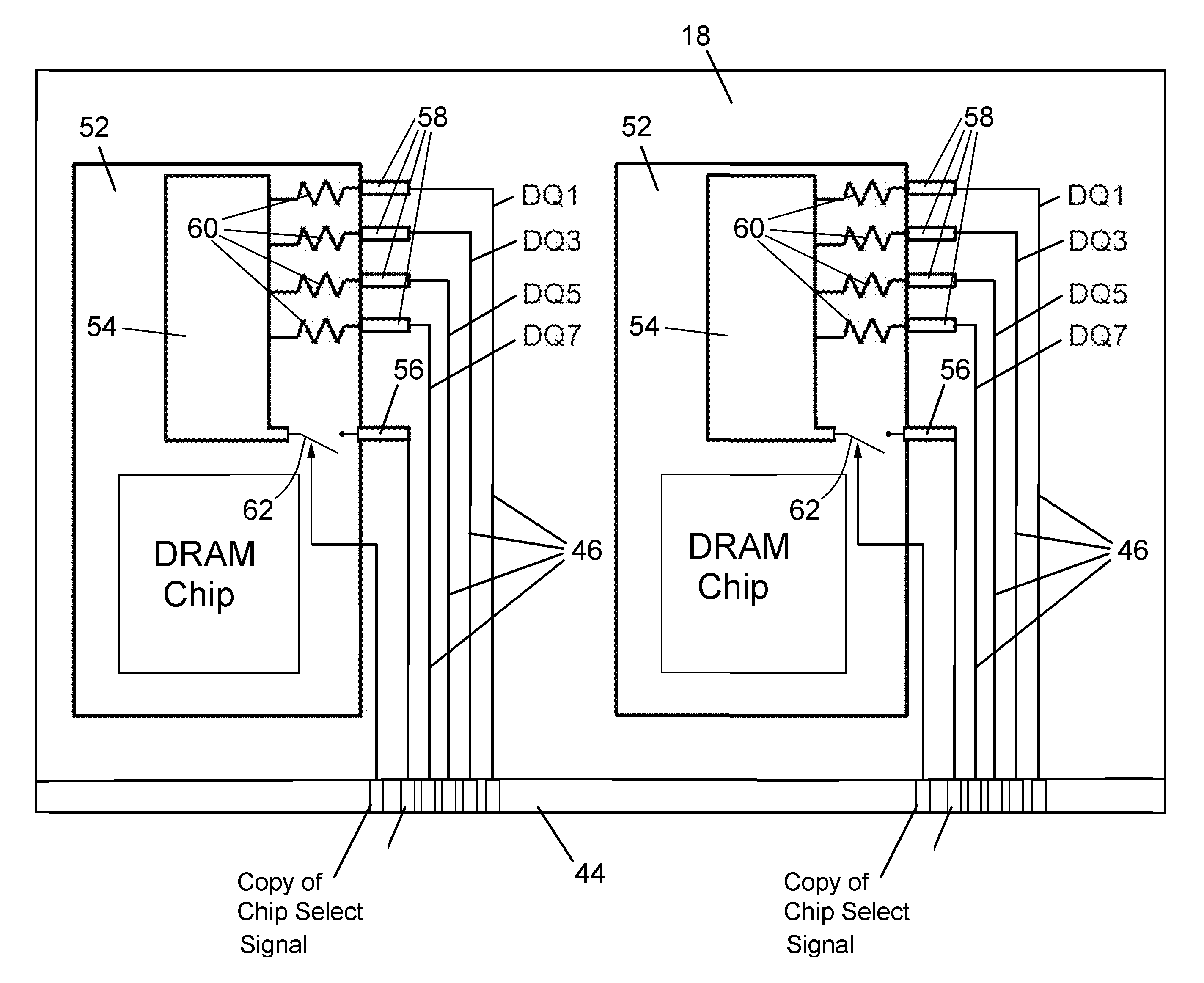
[0008]The present invention provides an approach to reducing noise and signal reflections through the use of termination resistors directly on or immediately adjacent the I / O pins of the memory components, and terminating the resistors to ground, supply voltage, or reference voltage.
[0011]According to an optional aspect of the invention, the termination resistors can be implemented in the form of a termination to the VRef value to help both high and low signal voltages to return to the crossover point much faster because of an additional push-pull mechanism for the high-low voltage swing. According to another optional aspect of the invention, the resistors can be terminated to the supply voltage (VDD or VSS) to account for asymmetries in the voltage swing, or a virtual termination voltage could be used that differs from VRef and can be adjusted above or below VRef to optimally compensate for asymmetries in the high-low voltage swing of the memory components used.
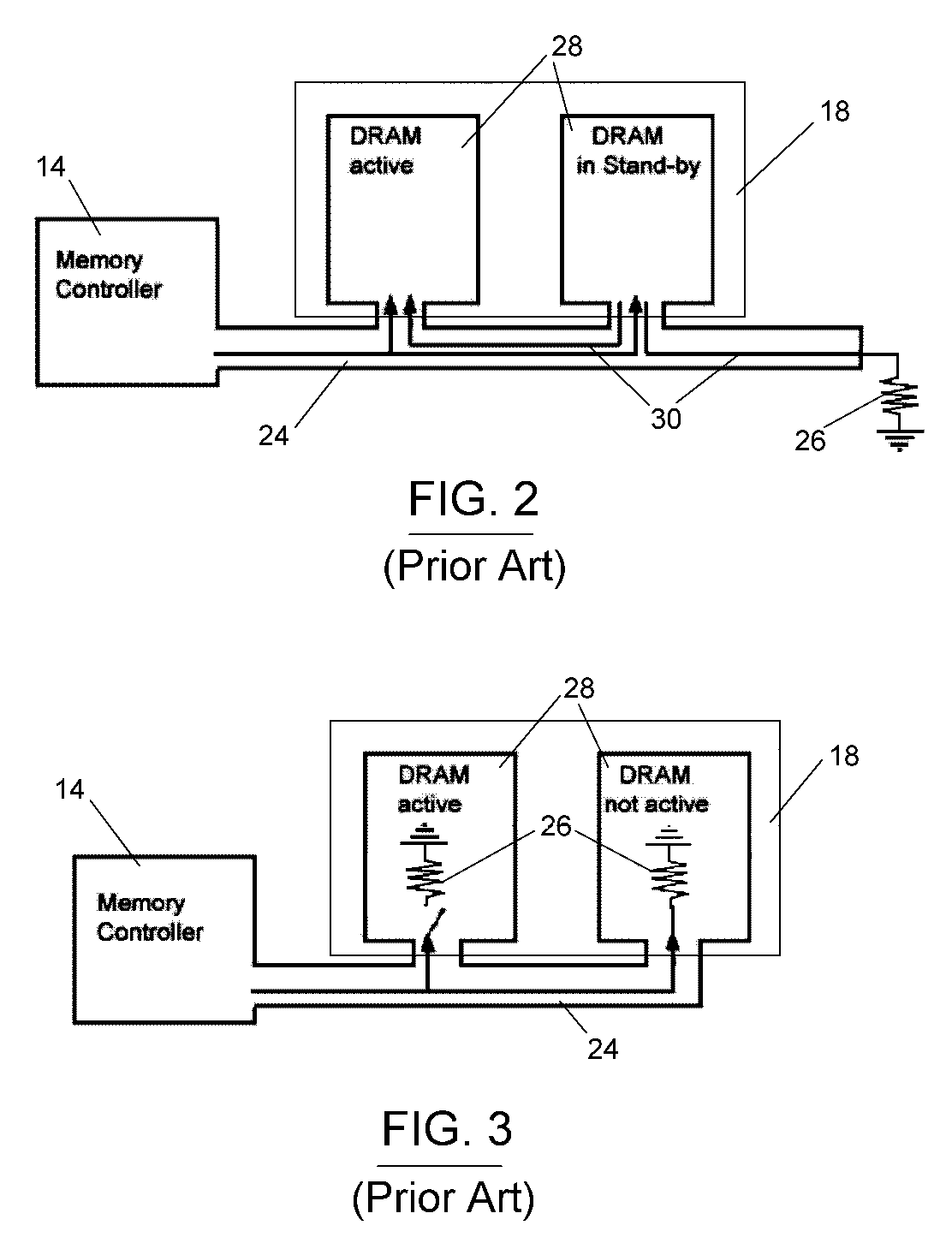
[0012]A shortcoming of static termination schemes is the constant passive current draw to the termination sink, which occurs regardless of whether the termination is at the level of the supply voltage, the ground or any termination voltage. In addition, termination of the signal itself will also weaken it and, therefore, have disadvantages in that it would require higher drive strength of the output buffers. For either reason, it can be advantageous to implement a switch to turn On or Off the termination depending on whether the devices are active or not. This type of dynamic termination is implemented in the on-die Termination of the DDR2 and later designs and reduces the passive power dissipation of the memory subsystem. Because of such benefits, the present invention encompasses an embodiment in which the chip select signal that selects the active physical bank within the memory subsystem (or another suitable signal) is used as a control signal to turn the termination On or Off.
[0013]In view of the above, the present invention provides for the elimination or at least significant reductions in signal reflections directly adjacent to the die, which results in faster termination of signals and freeing up the bus. Because the invention can be implemented by modifying only the memory module, such as the PCB, and does not require modifications to the mainboard or memory die, the invention offers the further advantage of backward compatibility with existing systems. According to optional aspects of the invention, the above advantages can be obtained while also adjusting for asymmetries of the memory component electrical characteristics.

Problems solved by technology

In view of the above, the termination is not on-die, though it occurs as close as possible to the die and will not allow contention of the bus with noise.

Method used


Image

  • Memory module having on-package or on-module termination
  • Memory module having on-package or on-module termination
  • Memory module having on-package or on-module termination

Examples


Embodiment Construction

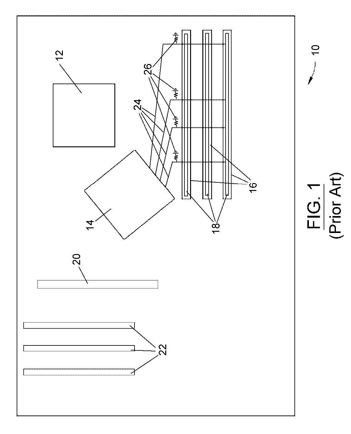
[0021]As previously discussed, the problem of signal reflections in memory subsystems of computers has typically been addressed in the past by adding termination resistors on the mainboard. Such an approach is depicted in FIG. 1, which shows a schematic layout of a computer mainboard 10, including a CPU socket 12 and a chipset containing a memory controller 14 connected to memory slots (sockets) 16 with data lines 24. Memory modules 18, such as single in-line memory modules (SIMM's) or dual in-line memory modules (DIMM's), are represented as being installed in memory slots 16. Also shown is a graphics interface 20 (AGP or PCIe or similar) and expansion slots 22. In accordance with conventional mainboard termination approaches to reducing signal reflection, each of the data lines 24 is schematically portrayed as being individually terminated to ground with a termination resistor 26. In practice, the positions of the termination resistors 26 will depend on the specific layout of the m...


PUM


Abstract

A memory module adapted for installation in an open memory socket on a mainboard of a computer. The memory module includes a substrate with an edge connector comprising pins along an edge of the substrate, and at least one memory package mounted to the substrate and containing a memory die electrically connected to input / output leads located along the perimeter of the memory package and through which data signals are transmitted to and from the memory die. Data signal lines electrically connect a plurality of the input / output leads of the memory package to a plurality of the pins of the edge connector. Termination resistors individually electrically connect each of the data signal lines to ground, a supply voltage, or a reference voltage of the memory package so as to reduce noise and signal reflections through the data signal lines.

Description

CROSS REFERENCE TO RELATED APPLICATIONS[0001]This application claims the benefit of U.S. Provisional Application No. 60 / 522,171, filed Aug. 25, 2004.BACKGROUND OF THE INVENTION[0002]The present invention generally relates to memory modules for installation in computer memory subsystems. More particularly, this invention relates to a memory module equipped with termination resistors located directly on or immediately adjacent the I / O pins of memory packages of the module to reduce noise and signal reflections.[0003]The computer industry has moved to higher speed grades not only in the field of processor technology but also relating to all peripheral devices including the system memory. The latter has become the main bottleneck in the overall system performance in that, with increasing clock rates, the central processors are starved for data and more and more cycles are wasted idly because of the lack of data and instructions to be processed.[0004]Memory clock and data frequency are l...

Claims


Application Information

Patent Timeline
Patent Type & Authority Patents(United States)
IPC IPC(8): H01R12/16
CPCG11C5/04G11C7/1051G11C7/1057G11C7/1078G11C7/1084H05K1/0246H05K2201/10022H05K2201/10522H05K2201/10689
Inventor PETERSEN, RYAN M.SCHUETTE, FRANZ MICHAEL
Owner KIOXIA CORP
Learn More