
Machine for pressure testing container

Inactive Publication Date: 2009-06-09
EMHART GLASS SA
View PDF10 Cites 12 Cited by
  • Summary
  • Abstract
  • Description
  • Claims
  • Application Information

AI Technical Summary

Benefits of technology

[0005]It is an object of the present invention to provide an inspection machine that can pressure test a glass bottle and provide the operator with key information in addition to the fact that the bottle has failed the pressure test.

Problems solved by technology

If the bottle is unable to be pressurized to this pressure the operator knows that there is a problem.

Method used


Image

  • Machine for pressure testing container
  • Machine for pressure testing container
  • Machine for pressure testing container

Examples


Embodiment Construction

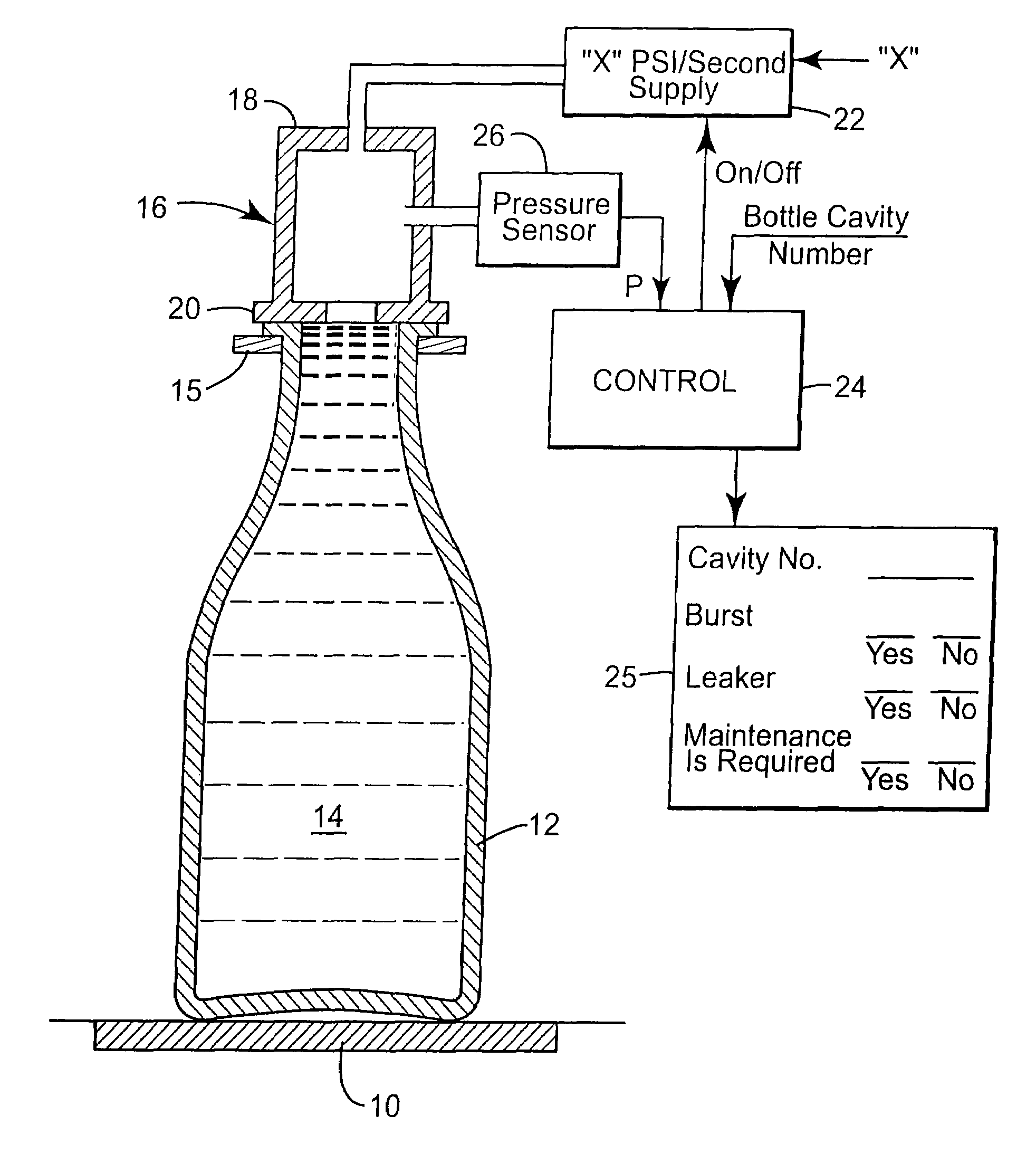
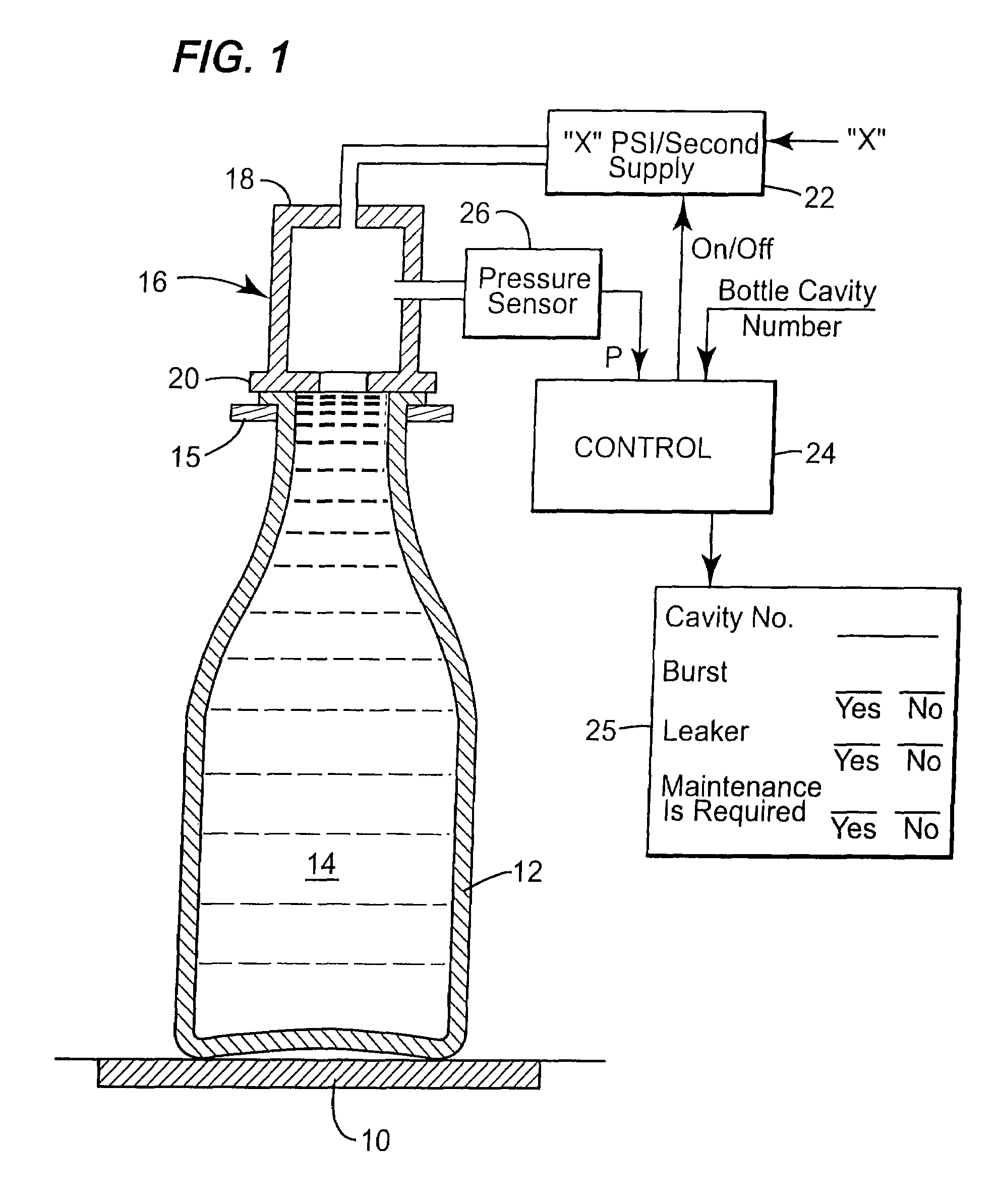
[0010]The inspection machine has a base 10 which is located at an inspection station. A bottle 12 filled with water 14, is delivered to the inspection station by a suitable delivery structure (here the gripping jaws 15 of one of the arms of a rotary feeder are shown). The water-filled bottle will be supported by the base 10. The inspection machine has a test head 16, which includes an upper inlet housing 18 and an annular sealing member 20. An “X” PSI / SECOND SUPPLY 22 / FIG. 2 (“X” is settable) supplies air to the pressure head. This supply will result in a pressure within the head which increases linearly (line 30, FIG. 3). A PRESSURE SENSOR 26 supplies pressure (P) sensed within the test head to the CONTROL 24. A mold number reader (not shown) supplies the BOTTLE CAVITY NUMBER for each bottle to be tested to the CONTROL 24.

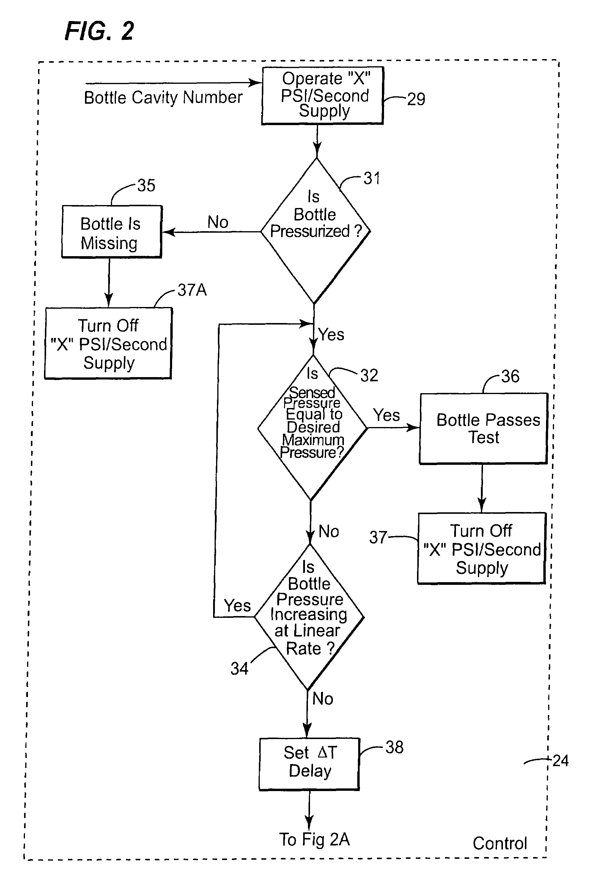
[0011]When a good bottle is tested, the CONTROL 24 will OPERATE “X” PSI / SECOND SUPPLY 29 (supply an “ON” signal) and pressure will increase in a substantially lin...


PUM


Abstract

An inspection machine for pressure testing a glass bottle filled with water. A normal test pressurizes the bottle until the pressure reaches an acceptable level. If the bottle bursts or leaks the pressure will not reach the acceptable level. A control monitors the pressure curve and can determine when a bottle bursts. The control can also determine that a leak is present and when the leak happens with “N” successive bottles, the control indicates that there is a maintenance problem.

Description

[0001]The present invention is a continuation-in-part of U.S. Patent Application Ser. No. 60 / 827,009, filed Sep. 26, 2006, now abandoned.[0002]The present invention relates to machines for inspecting glass containers to provide feedback information to be used by an operator to modify the performance of the machine that produced the container.BACKGROUND OF THE INVENTION[0003]It is important that a glass bottle, to be filled with a liquid under pressure, be sufficiently strong that it will not fail in use.[0004]Prior art systems that pressure test a glass bottle or container, fill the bottle with water and apply pressure at a selected rate until a defined pressure exists within the bottle. If the bottle is unable to be pressurized to this pressure the operator knows that there is a problem.OBJECT OF THE INVENTION[0005]It is an object of the present invention to provide an inspection machine that can pressure test a glass bottle and provide the operator with key information in addition...

Claims


Application Information

Patent Timeline
Patent Type & Authority Patents(United States)
IPC IPC(8): G01M3/02
CPCG01M3/3263
Inventor THOMAS, ALAN E.BAGLEY, MICHAEL C.SPITERI, PHILIPPEOTTO, RICHARD B.
Owner EMHART GLASS SA
Learn More