Self-calibrating pressure sensor

a self-calibrating, pressure sensor technology, applied in the direction of fluid pressure measurement using elastically deformable gauges, instruments, mechanical elements, etc., can solve the problems of diaphragm based pressure sensors suffering calibration drift, sensor failure, sensor partial or total failure, etc., to achieve the effect of improving process efficiency, operational cost, and reliability

Inactive Publication Date: 2009-06-09
ADVANCED RES
View PDF6 Cites 17 Cited by
  • Summary
  • Abstract
  • Description
  • Claims
  • Application Information

AI Technical Summary

Benefits of technology

[0011]The sensor may be integrated into a wireless package for ease of implementation and replacement of outdated sensors. Due to its capabilities, manufactured sensors of this type can self-calibrate without the benefit of traditional calibration against a standard. These self diagnostic and determination capabilities provide better long-term system accuracy and targeted maintenance schedules, improving process efficiency, operational cost, and reliability.

Problems solved by technology

In use, pressure sensors can drift in their calibration outside of their desired accuracy for the application.
A sensor might also suffer partial or total failure.
Diaphragm based pressure sensors are known to suffer from calibration drift over time.
Most calibration-slope drift problems are related to changes in the diaphragm's mechanical properties.
Compensation for temperature calibration offsets has been developed to a high degree, but little has been done to address changes in the mechanical properties of the diaphragm.

Method used


Image

  • Self-calibrating pressure sensor
  • Self-calibrating pressure sensor
  • Self-calibrating pressure sensor

Examples


Embodiment Construction

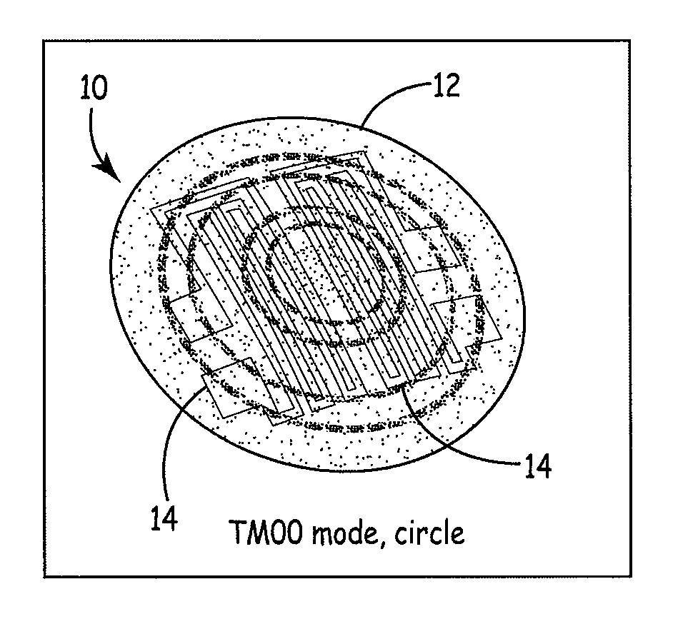
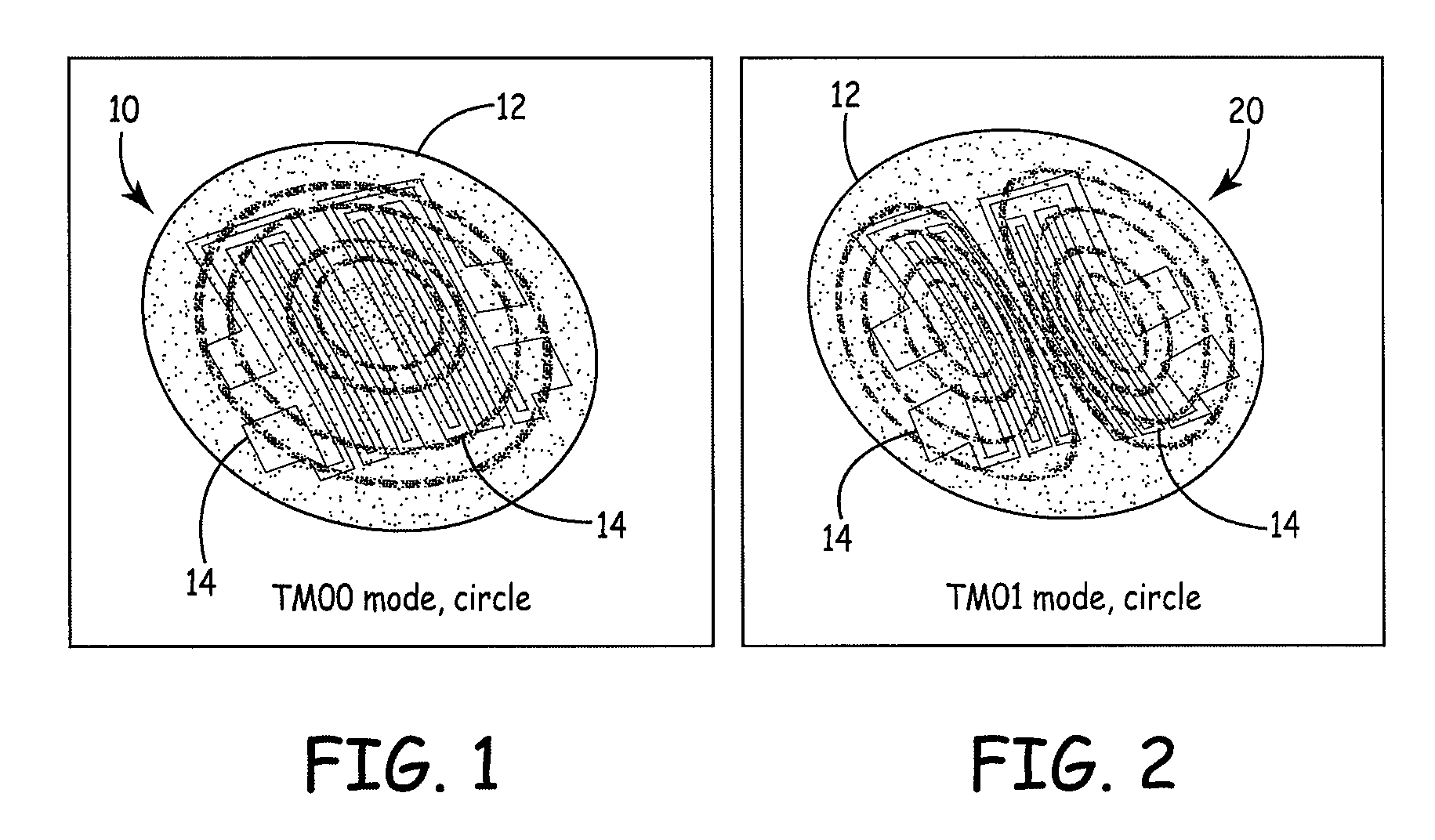
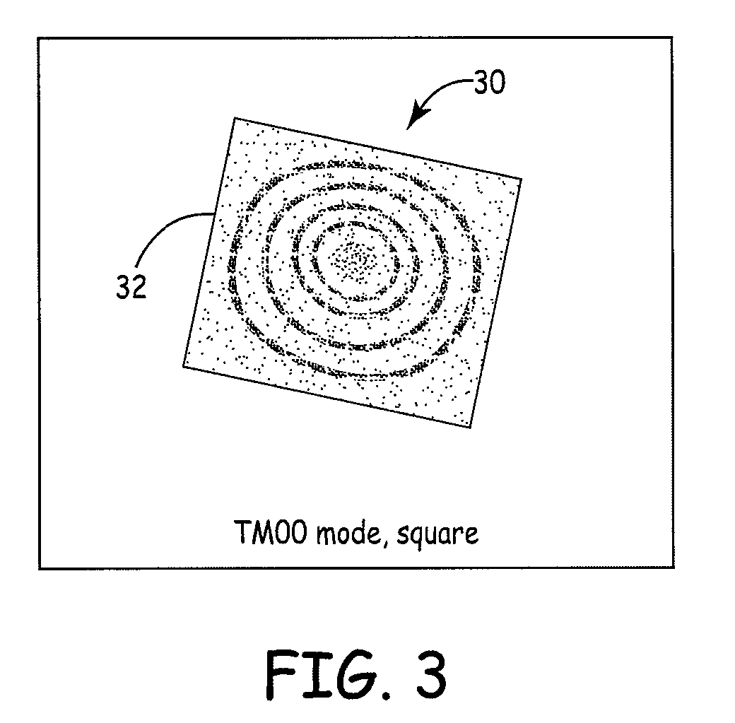
[0022]The present invention is a novel and advantageous self-calibrating sensor. The present invention can be applied to, for example, a self-calibrating pressure sensor, in which a deformation of a diaphragm can be detected and self-calibrated. Although the present invention is described herein with respect to a self-calibrating pressure sensor, the principles apply, in general, to other types of sensors used to measure physical quantities, such as, but not limited to, temperature, light intensity, radiation, force, position or other mechanical movements, such as vibration, sound, acceleration and rotation. The pressure sensor of the present invention may be used for, but not limited to, medical equipment, HVAC equipment, process controls, industrial machinery, pumps, robotics, etc.

[0023]Generally, the category of pressure sensors considered here, are constructed of a flexible diaphragm with strain gauges bonded to, or diffused into, it, acting as resistive elements. As the pressur...


PUM

PropertyMeasurementUnit
pressureaaaaaaaaaa
frequency shiftaaaaaaaaaa
frequencyaaaaaaaaaa

Abstract

The present invention is system and method for providing a self-calibrating pressure sensor. A pressure sensor apparatus comprises a diaphragm, at least one driving element operably coupled to the diaphragm configured to induce deflection in the diaphragm, and at least one strain gauge coupled to the diaphragm. The at least one strain gauge measures the deflection of the diaphragm. Typically, the driving elements will be piezoelectric drivers and will be operably coupled to the diaphragm. A method for evaluating a pressure sensor comprises inducing deflection in a diaphragm, measuring the deflection, determining the frequency-dependent response, calculating mechanical characteristics of the diaphragm from the frequency-dependent response, and calculating a response coefficient for the diaphragm based in part on said mechanical characteristics. The response coefficient is used to evaluate the sensor. The sensor can then be re-calibrated or self-calibrated based on the response coefficient.

Description

CROSS-REFERENCE TO RELATED APPLICATION(S)[0001]This application claims priority to U.S. provisional patent application Ser. No. 60 / 730,563, filed Oct. 27, 2005, which is incorporated herein by reference in its entirety.FIELD OF THE INVENTION[0002]The present invention relates to a self-calibrating sensors that have their output electronically calibrated. More particularly, the present invention relates to a sensor having a diaphragm, at least one piezoelectric element coupled to the diaphragm configured to induce deflection in the diaphragm, and at least one piezoresistive element coupled to the diaphragm, wherein the at least one piezoresistive element measures the deflection of the diaphragm.BACKGROUND OF THE INVENTION[0003]In use, pressure sensors can drift in their calibration outside of their desired accuracy for the application. A sensor might also suffer partial or total failure. Diaphragm based pressure sensors are known to suffer from calibration drift over time. This can m...

Claims


Application Information

Patent Timeline
Patent Type & Authority Patents(United States)
IPC IPC(8): G01L7/08
CPCG01L27/007
Inventor COTTLES, VERNON MICHAELWAGNER, GREGORY LAWRENCE
Owner ADVANCED RES
Why Eureka
Try Eureka