
Built-in tool magazine structure

A technology of tool magazine and inner cavity, which is applied in the field of built-in tool magazine structure, can solve the problems of column deformation, unfavorable machine tool accuracy, and long auxiliary tool change time, and achieve the effects of reducing distortion, improving processing efficiency, and maintaining accuracy

Inactive Publication Date: 2016-09-07
滕州博信机床有限公司
View PDF7 Cites 0 Cited by
  • Summary
  • Abstract
  • Description
  • Claims
  • Application Information

AI Technical Summary

Problems solved by technology

[0002] Most of the tool magazines of existing vertical machining centers are installed on one side outside the column. When changing tools for machine tools with a large processing area, the spindle slide needs to move to the position where the tool magazine is located to change tools. The auxiliary time for tool changing is too long. At the same time, the tool magazine is installed on one side of the column, so that the loads on both sides of the column are inconsistent. Long-term use will easily lead to deformation of the column, which is not conducive to maintaining the accuracy of the machine tool.

Method used


Image

  • Built-in tool magazine structure
  • Built-in tool magazine structure

Examples


Embodiment Construction

[0012] The present invention will be further described below in conjunction with accompanying drawing and specific embodiment:

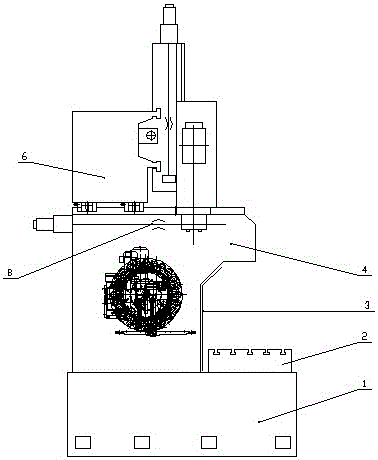
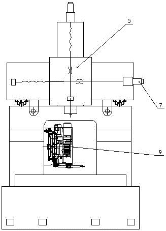
[0013] A built-in tool magazine structure, such as figure 1 As shown, it includes: a workbench 2 and a base 1, the workbench 2 and the base 1 are an integrated structure, the base 1 is equipped with a column 4, the column 4 adopts a wide body design, and the interior is an arch bridge structure, The bridge-shaped inner cavity of the column 4 is installed with a disc tool magazine 9, and the disc tool magazine 9 is fixed on the column 4 with a tool magazine bracket, and the X-axis servo motor 7 and the main shaft are installed on the column 4. Skateboard 5, Y-direction crossbeam 6 and double lead screw 8, described X-axis servo motor 7 can drive main shaft slide plate 5 to the position of disc tool magazine 9, Y-direction crossbeam 6 moves and adopts double lead screw 8 driving structure.

[0014] In this embodiment: an automatic door 3 is installed ...


PUM


Abstract

The invention relates to a built-in tool magazine structure. The built-in tool magazine structure comprises a working table and a base, wherein the working table and the base are of an integral structure; an upright post is arranged on the base, and adopts a wide-body design; the interior of the base is of an arch bridge-shaped structure; a disk tool magazine is arranged at a bridge-shaped inner cavity of the upright post; the disk tool magazine is fixed on the upright post by using a tool magazine bracket; an X-axis servo motor, a main shaft sliding plate, a Y-direction cross beam and double lead screws are arranged on the upright post; the X-axis servo motor can drive the main shaft sliding plate to the position where the disk tool magazine is; the Y-direction cross beam adopts a driving mechanism with the double lead screws. The built-in tool magazine structure has the advantages that the boundary dimension of a machine tool can be reduced, the tool changing auxiliary time is short, the tool changing efficiency is improved, and the strength and rigidity of the machine tool are increased.

Description

technical field [0001] The invention relates to a tool magazine installation structure of a vertical machining center, in particular to a built-in tool magazine structure. Background technique [0002] Most of the tool magazines of existing vertical machining centers are installed on one side outside the column. When changing tools for machine tools with a large processing area, the spindle slide needs to move to the position where the tool magazine is located to change tools. The auxiliary time for tool changing is too long. At the same time, the tool magazine is installed on one side of the column, so that the loads on both sides of the column are inconsistent. Long-term use will easily lead to deformation of the column, which is not conducive to maintaining the accuracy of the machine tool. Contents of the invention [0003] The purpose of the present invention is to provide a built-in tool magazine structure which reduces the overall size of the machine tool, shortens ...

Claims


Application Information

Patent Timeline
Patent Type & Authority Patents(China)
IPC IPC(8): B23Q3/155B23Q1/01B23Q5/40
CPCB23Q1/015B23Q3/155B23Q5/40
Inventor 王彬刘良选
Owner 滕州博信机床有限公司
Learn More