Methods and apparatus for aerodynamic and hydrodynamic drag reduction and attitude control for high speed boats

a technology of hydrodynamic drag reduction and attitude control, which is applied in the field of high-speed boats, can solve the problems of unavoidably aerodynamic drag induced, adverse pressure gradients the (viscid) airflow imposes on the (viscous) boundary layer will be too great for the flow to remain attached, and the hydrodynamic pressure drag is reduced, so as to reduce the hydrodynamic wetted area, reduce the hydrodynamic drag, and reduce the effect of aerodynamic and aerodynamic drag

Inactive Publication Date: 2009-06-09
FLOW WORKS
View PDF22 Cites 32 Cited by
  • Summary
  • Abstract
  • Description
  • Claims
  • Application Information

AI Technical Summary

Benefits of technology

[0032]The present invention provides methods and apparatus for reducing hydrodynamic and aerodynamic drag in addition to controlling the attitude of high-speed boats using multiple wings. By providing aerodynamic lift, the required hydrodynamic lift and hence the hydrodynamic pressure drag is reduced. Additionally, the aerodynamic lift reduces the hydro-dynamically wetted area and hence also reduces the hydrodynamic skin-friction drag. Typically, when generating aerodynamic lift, unavoidably aerodynamic drag is induced. In the present invention such aerodynamic drag is offset by aerodynamic drag reduction through base-pressure increases of the transom achieved by the use of the generally undesirable downwash inherent to generating high lift with airfoils. Additionally, eroding the hull shape around the bow for mono (v) type hulls in high static-pressure areas allows forward lift-generating elements to provide synergy without the need for drag-generating wing-support and adjustment structures. Using wings as leading-edge of the roof of the tunnel or tunnels in a multi-hull boat such as a catamaran provides synergy by allowing lift generation in the front of the boat in addition to controlling airflow into the tunnel or tunnels without the need for drag-generating wing-support and wing-adjustment structures and without increasing the aerodynamic cross section. Aerodynamic-drag minimization can be further enhanced through wake management using downwash from horizontal wings mounted near the deck and vertical wings mounted on the freeboard in the vicinity of the transom. The performance of low-aspect ratio wings used in the present invention can profit from wavy leading edges which essentially compartmentalizes lift between troughs. Using aerodynamic channels eroded or carved out from the deck shape and the freeboard shape, the aft wings can be also supported and adjusted without the need for drag-generating structures. The use of independently adjustable wings (forward, aft, port and starboard) will provide a means to not only control sinkage and wetted surface, but also trim, heel, and yaw angles of the hull.
[0033]More particularly, the present invention is directed to methods and apparatus for integrating airfoils into a VHS boat hull to generate lift and reduce overall drag simultaneously through the advantageous use of airfoil-induced flows and by judicial erosion of the hull at the bow to avoid high stagnation-pressure areas. In particular, the high speeds VHS boats achieve allow appropriate airfoils to generate a significant fraction of the hull weight in aerodynamic lift. Although a reduction in sinkage and wetted surface, and thus a reduction in hydrodynamic pressure drag and hydrodynamic skin drag will be achieved, this would normally be offset by the induced aerodynamic drag which is fundamentally tied to generating lift with airfoils. Typically, the higher the lift generated the higher the induced drag. With an example embodiment of the present invention, more lift from a given total airfoil surface area is achieved by using multiple airfoils. Here the flow leaving the high-pressure side at the trailing edge of the first airfoil energizes the boundary layer of the suction side of the downstream airfoil. Of course, in accordance with the present invention, a third similarly arranged airfoil downstream of the second airfoil could be added and so on. This arrangement allows extreme angles of attack of these downstream airfoil(s) without the risk of lift-destroying and drag-inducing flow-separation at the suction side of the said downstream airfoil(s). The higher the lift the higher the downward motion of the air leaving the wing comprised of one or more airfoils in the above described arrangement. To prevent tip losses in these relatively low-aspect ratio airfoil systems, generally, endplates or winglets are fitted.

Problems solved by technology

Typically, when generating aerodynamic lift, unavoidably aerodynamic drag is induced.
Typically, the higher the lift generated the higher the induced drag.
If we consider the flow attached at the transom area when the boat is starting to move, the adverse pressure gradients the (inviscid) airflow imposes on the (viscous) boundary layer will be too great for the flow to remain attached.
In addition, the separation point may move in response to pressure gradients imposed by unsteady flow features in the wake.

Method used


Image

  • Methods and apparatus for aerodynamic and hydrodynamic drag reduction and attitude control for high speed boats
  • Methods and apparatus for aerodynamic and hydrodynamic drag reduction and attitude control for high speed boats
  • Methods and apparatus for aerodynamic and hydrodynamic drag reduction and attitude control for high speed boats

Examples


example i

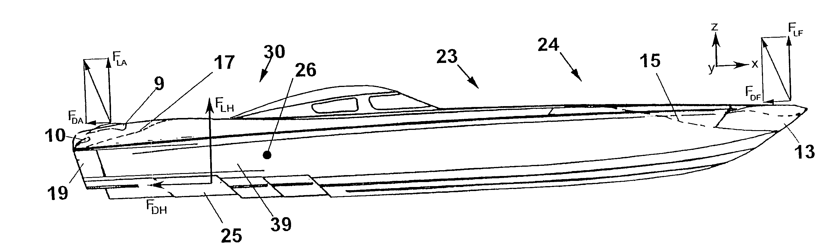
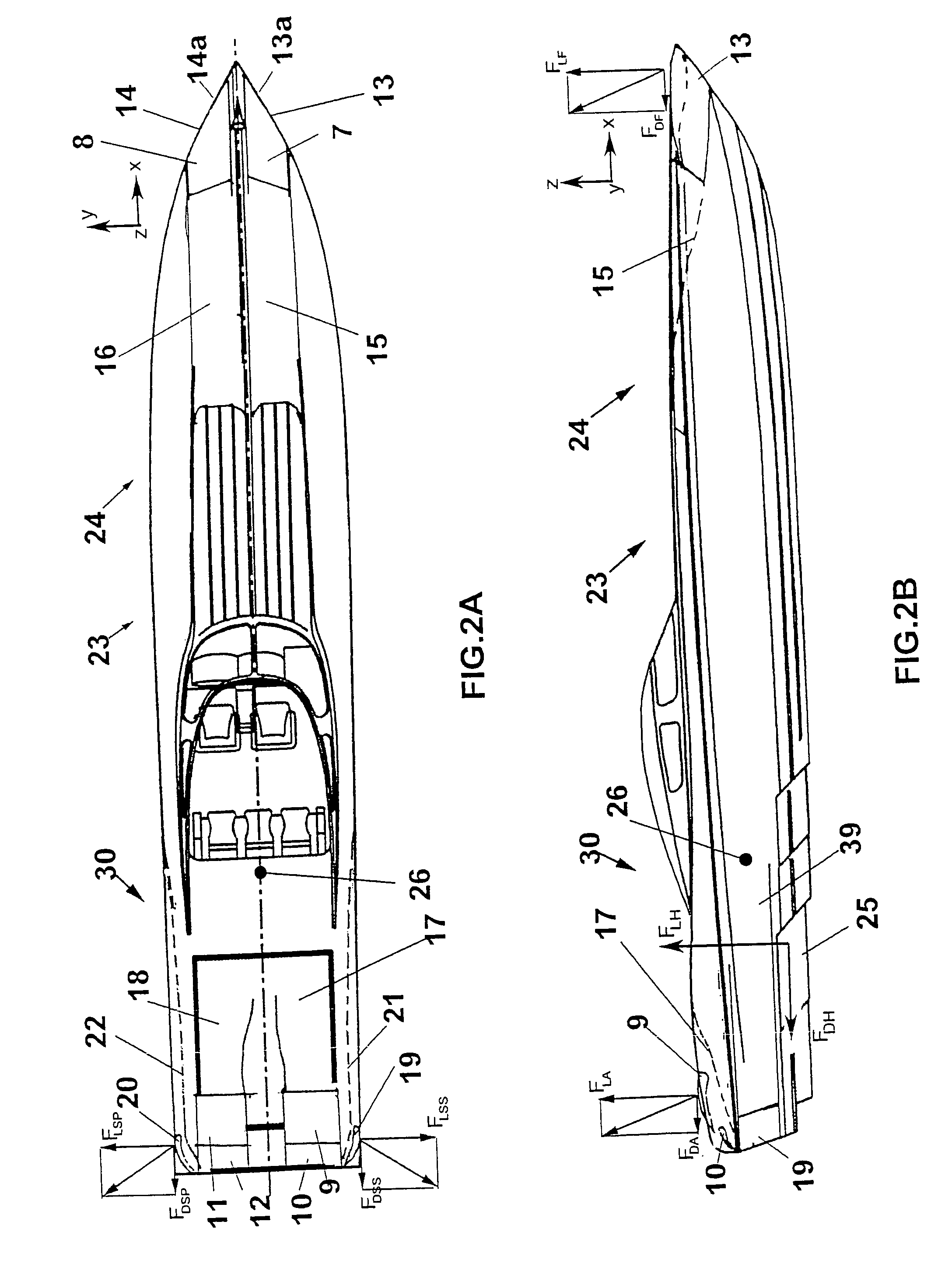
[0106]To demonstrate the advantages of various example embodiments of the present invention, a wing system was designed for a 47 foot, 9800 lbs powerboat, similar to the example embodiment of the power boat 23 shown in FIG. 2. For the bow, a transonic wing profile was selected with an area of 0.6 m2 for both the starboard wing 7 and the port wing 8, each wing having a 6° angle of attack. For the transom a staggered stack of two wings was selected with areas of 0.26 m2 and 0.1 m2, respectively, for the stack of starboard wings 9, 10 and for the stack of port wings 11, 12, each set of wings having angles of attack at 14° and 36°, respectively. The estimated lift generated as a function of boat velocity is shown by curve 101 in FIG. 11 for the bow wings 7, 8 and by curve 102 in FIG. 12 for the transom wings 9, 10, 11, 12. In this particular example, the bow wings have an airfoil profile DLRF-R4 and the transom stacks of wings have an airfoil profile FX76MP14. The particular selection s...

example ii

[0107]To illustrate the effectiveness of the example embodiment of the present invention utilizing a single leading-edge wing at the leading edge of a tunnel hull of a catamaran, an example wing system in accordance with the present invention was designed for a 40 foot, 8500 lbs catamaran. The particular catamaran used for this example, in its prior-art form, has a tunnel width of 66 inches, a tunnel height at the front of 66 inches and a tunnel height at the back of 44 inches. The benefits of example embodiments of the present invention are illustrated by the effect of a leading-edge wing to decrease the ability of the tunnel-generated forces to lift the hull off the water in addition to decrease the ability of the tunnel-generated forces to rotate the bow up and around the center of inertia (“blow over” event).

[0108]FIG. 14 shows, as a function of catamaran attitude (the angle of the longitudinal axis of inertia of the boat with respect to the water) at 160 mph, the lift generated...


PUM


Abstract

The present invention provides methods and apparatus for reducing sinkage and wetted surface, and thus hydrodynamic drag of a high-speed boat through the generation of aerodynamic lift while decreasing overall aerodynamic drag. At least one lift-generating front wing proximate a bow section of the boat with at least one corresponding front air channel may be provided. At least one lift-generating rear wing proximate a transom section of the boat with at least one corresponding rear air channel may also be provided. At least one of the wings may be adjustable to generate aerodynamic lift with one of: (1) a neutral; (2) a transom-lifting; and (3) a bow-lifting pitching moment about a center of inertia of the boat. At least one wing proximate the leading edge of the tunnel of a multi-hull boat may be provided to increase the operational envelope.

Description

FIELD OF THE INVENTION[0001]The present invention relates generally to the field of high-speed boats. In particular, the present invention provides methods and apparatus for reducing hydrodynamic and aerodynamic drag in addition to extending the operational envelope of high-speed boats by controlling the attitude, yaw, and rolling of high-speed boats using multiple wings.BACKGROUND OF THE INVENTION[0002]The performance of a high-speed vessel is intimately linked to the orientation of the hull at speed. Planing hulls mostly rise and change trim angle in response to the hydrodynamic pressure field generated by the hydrodynamic flow. Conversely, the hydrodynamic pressure field acting on the wetted part of the hull is affected by the design of the hull form (See, e.g., U.S. Pat. Nos. 5,452,676; 5,456,202; 5,685,253; and 5,685,253). Generally, the major contributors to drag for a high-speed boat are due to the hydrodynamic pressure field (hydrodynamic pressure drag) and the hydrodynamic ...

Claims


Application Information

Patent Timeline
Patent Type & Authority Patents(United States)
IPC IPC(8): B63B1/16
CPCB63B1/322Y02T70/12B63B39/005B63B39/04Y02T70/10
Inventor YAP, LOO T.
Owner FLOW WORKS
Why Eureka
Try Eureka