In-vehicle mount radar device

a radar device and vehicle-mounted technology, applied in the direction of antenna details, instruments, antennas, etc., can solve the problems of limited space, affecting the reception intensity of beat signals, and limited angle resolution, so as to enhance angle resolution and enhance angle information calculation precision

Active Publication Date: 2009-06-09
MITSUBISHI ELECTRIC CORP
View PDF6 Cites 61 Cited by
  • Summary
  • Abstract
  • Description
  • Claims
  • Application Information

AI Technical Summary

Benefits of technology

[0011]Therefore, an object of the present invention is to provide an in-vehicle mount type radar device that can enhance angle resolution in a limited antenna size and also further enhance the calculation precision of angle information.
[0013]According to the in-vehicle mount radar device of the present invention, the reception antenna array is constructed by arranging the plural reception antennas so that the reception antennas are spaced from one another at the interval d, each of the two transmission antennas is disposed so as to be spaced from the reception antenna located at each of both the end portions of the reception antenna array at the interval D, and the interval D is set to any value larger than the interval d. Accordingly, the antenna aperture diameter can be equivalently further increased, and the angle information concerning the target can be calculated with higher precision.

Problems solved by technology

However, the reception intensity of the beat signal is liable to be affected by various factors.
However, the in-vehicle mount radar device in which an antenna device must be disposed in a limited space has limited angle resolution because the space is restricted.

Method used


Image

  • In-vehicle mount radar device
  • In-vehicle mount radar device
  • In-vehicle mount radar device

Examples


first embodiment

(5) Effect of First Embodiment

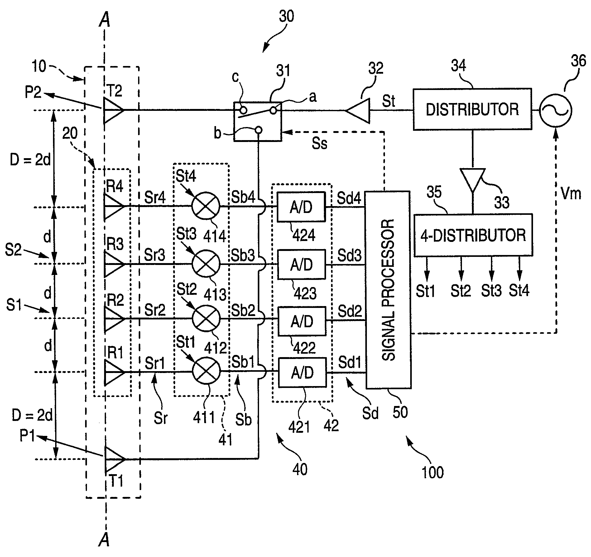
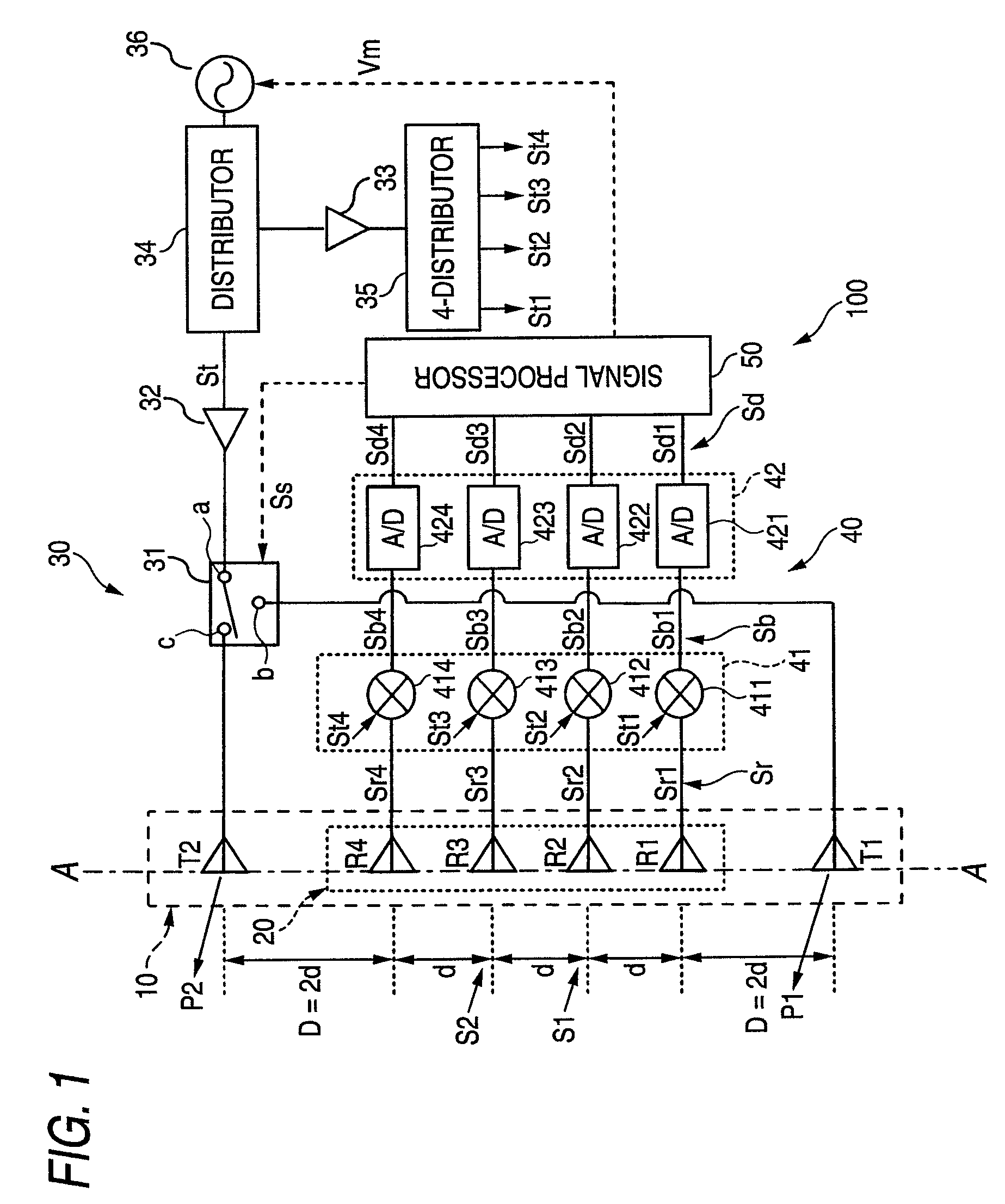
[0086]In the first embodiment, the angle information Iθ concerning the target is calculated by averaging the angle information Iθ1 to Iθ4 calculated from each reception channel pair. The resolution Δθ of the angle information Iθ1 to Iθ4 is defined as Δθ=(λ / L). In the first embodiment, the interval D between the transmission antennas T1, T2 and the reception antenna array 20 is set to D=2d with respect to the interval d of the reception antennas R1 to R4. As a result, the antenna aperture diameter L is increased and L is equal to 7d. Accordingly, the resolution Δθ can be enhanced to a smaller value, and thus more accurate angle information Iθ can be achieved.

[0087]Next, an effective angle measuring range Rθ of the in-vehicle mount radar device 100 will be described. The effective angle measuring range Rθ is an angle range in which the in-vehicle mount radar device 100 can accurately measure the angle information Iθ concerning the target on the basis of t...

second embodiment

[0091]In a second embodiment, the coefficient m is set to 2.5, and in connection with this setting, the positioning coefficient P is set to P=+16. The other constructions are the same as the first embodiment.

[0092]FIGS. 7A-7E show the route difference of the respective antennas and the equivalent arrangement of the antennas in the second embodiment. FIGS. 7A-7E correspond to FIGS. 3A-3E. However, in the second embodiment, the coefficient m is set to 2.5, and thus the typical route difference is different, and the interval of the virtual transmission antenna T1 / T2 in the equivalent arrangement of the antennas is different. The other conditions are the same as FIGS. 3A-3E.

[0093]In the second embodiment, the coefficient m is set to 2.5, and the interval D is set to 2.5d. Therefore, the reception antennas R1 to R4 are arranged along the arrangement line A-A of the antennas so as to be spaced from the transmission antenna T2 at intervals of 5.5d, 4.5d, 3.5d, 2.5d, respectively. According...

third embodiment

[0106]In the second embodiment, the coefficient m is set to 2.5. However, in a third embodiment, the coefficient m is set to 2.7, and in connection with this setting, the positioning coefficient P is set to 16.8. The other conditions are the same as the first embodiment.

[0107]In the third embodiment, as in the case of the first embodiment, the signal processor 50 is configured to executed the DFT processing on the reception data Sd in step S13 of FIG. 4. It may be considered that FFT processing is executed in place of DFT processing in step S13. However, in the FFT processing, it would be impossible to process the reception data in the channel direction of the space in step S4 unless the coefficient m is equal to an integral multiple of ½. In the third embodiment, the coefficient m is equal to 2.7 and thus this value is not an integral multiple of ½. However, by executing the DFT processing on the reception data in step S13 in the signal processor 50, it would be possible to process...


PUM


Abstract

In an in-vehicle mount radar device which has a reception antenna array containing plural reception antennas and two transmission antennas and in which a transmission pulse is time-divisionally and alternately transmitted from each of the two transmission antennas, a reception pulse based on the transmission pulse reflected from a target is received by each of the reception antennas, and at least angle information concerning the target is calculated by using reception data obtained by each reception antenna, the reception antenna array is constructed by arranging the plural reception antennas so that the reception antennas are spaced from one another at an interval d, each of the two transmission antennas is disposed so as to be spaced from the reception antenna located at each of both the end portions of the reception antenna array at an interval D, and the interval D is set to any value larger than the interval d.

Description

BACKGROUND OF THE INVENTION[0001]1. Field of the Invention[0002]The present invention relates to an in-vehicle mount radar device which is mounted in a vehicle or the like, and particularly to an in-vehicle mount radar device which is configured to calculate at least angle information concerning a target.[0003]2. Description of the Related Art[0004]Angle information concerning a target is information representing a direction to an existing target, and it is generally obtained by sweeping a beam in the in-vehicle mount radar device.[0005]A beam is mechanically swept in a mechanical scanning system, for example. According to this mechanical scanning system, a target is detected in an area in which beams are overlapped with each other with respect to two reception antennas, and angle information concerning the target is obtained on the basis of the reception intensity of the beat signal in each area. However, the reception intensity of the beat signal is liable to be affected by variou...

Claims


Application Information

Patent Timeline
Patent Type & Authority Patents(United States)
IPC IPC(8): G01S13/93G01S13/931
CPCG01S13/426H01Q1/3233H01Q3/26G01S13/931G01S2013/0245
Inventor MATSUOKA, KATSUJI
Owner MITSUBISHI ELECTRIC CORP
Why Eureka
Try Eureka