
Floodwater barrier

a technology of water barrier and sluice chamber, which is applied in the direction of flood panels, shutters/movable grilles, wing frames, etc., can solve the problems of large damage, large damage, and damage to crops, roadways and other externally located constructions, and achieve the effect of improving the water sealing properties of the apparatus, increasing the strength of the seal, and rapid assembly

Inactive Publication Date: 2009-06-16
FLOODARK
View PDF19 Cites 16 Cited by
  • Summary
  • Abstract
  • Description
  • Claims
  • Application Information

AI Technical Summary

Benefits of technology

[0013]whereby, when it is anticipated that flood waters will rise high enough to penetrate an aperture of a building, the housing is fixed into position around a portion of the periphery of the aperture, the barrier member sealingly engages and co-operates with the housing to form a barrier to prevent floodwater entering the aperture.
[0021]The or each barrier member can include one or more barrier member-engaging portions to enable a number of barrier members to be fitted together to form a barrier of increased size. The barrier can thus be increased in height sequentially, as the height of the flood water rises. The step-wise assembly of a barrier, has a number of advantages. Firstly the problems of transportation and storage of a number of smaller barrier sections is smaller than is the case when one large section is involved. Secondly, where an eventually high flood water level is expected, but the level is still at a relatively low level, the aperture may continue to be used with the minimum of difficulty.

Problems solved by technology

Floodwaters, particularly from swollen rivers and high tides can cause widespread and costly damage.
The damage caused is not only to crops, roadways and other externally located constructions which become at least partially submerged, but also to the interiors of properties such as warehouses or domestic dwellings.
The apparent increase in the frequency of floodwater causing such damage has highlighted the costs involved in reparation and that these costs are borne principally by insurance companies or property owners.
The problem of the flooding of domestic dwellings has recently increased, due to changes in government policy regarding where new housing may be located.
However, due to the increased drive towards the construction of new homes and the lack of suitable space now available, the criteria for assessing whether land is fit for the purposes, of construction have been relaxed and an increasing number of buildings are now at risk.
The streams and rivers therefore reach a higher water level, more rapidly than was previously the case, placing buildings, which were formerly safe from flooding, at risk.
This can however be a difficult and arduous task and is not at all suitable for those who are infirm or who have difficulty in lifting and maneuvering the sand bags into position.
Moreover, once the flood water has passed, the user is then left with the problem where to store the sand bags and also with the problem of how to prevent the material from which the bag itself is formed from rotting.
The latter problem is particularly acute where sacking is used to form a bag.
Due to the close engagement of the act of pushing a barrier into a U-shaped channel can be difficult and also cause damage to the sealing material due to friction.

Method used


Image

  • Floodwater barrier
  • Floodwater barrier
  • Floodwater barrier

Examples


Embodiment Construction

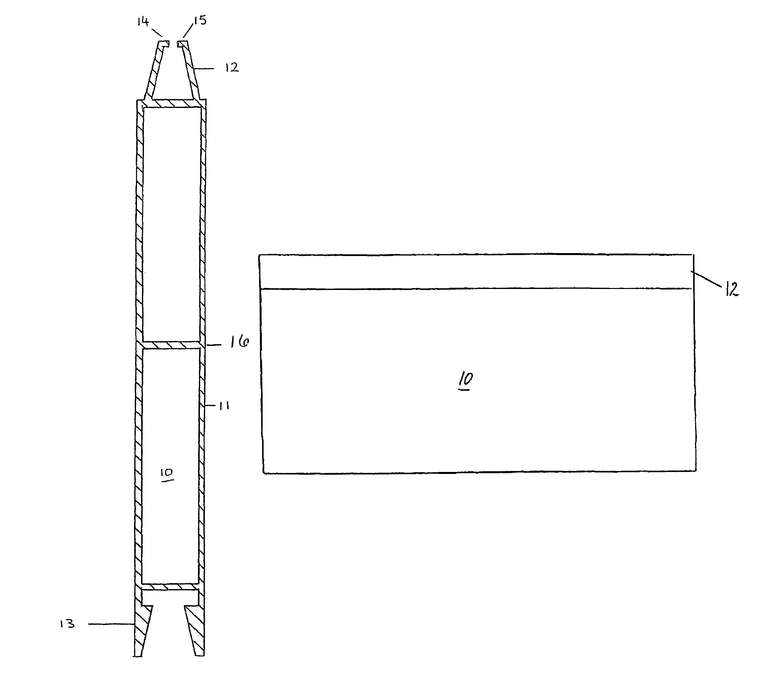
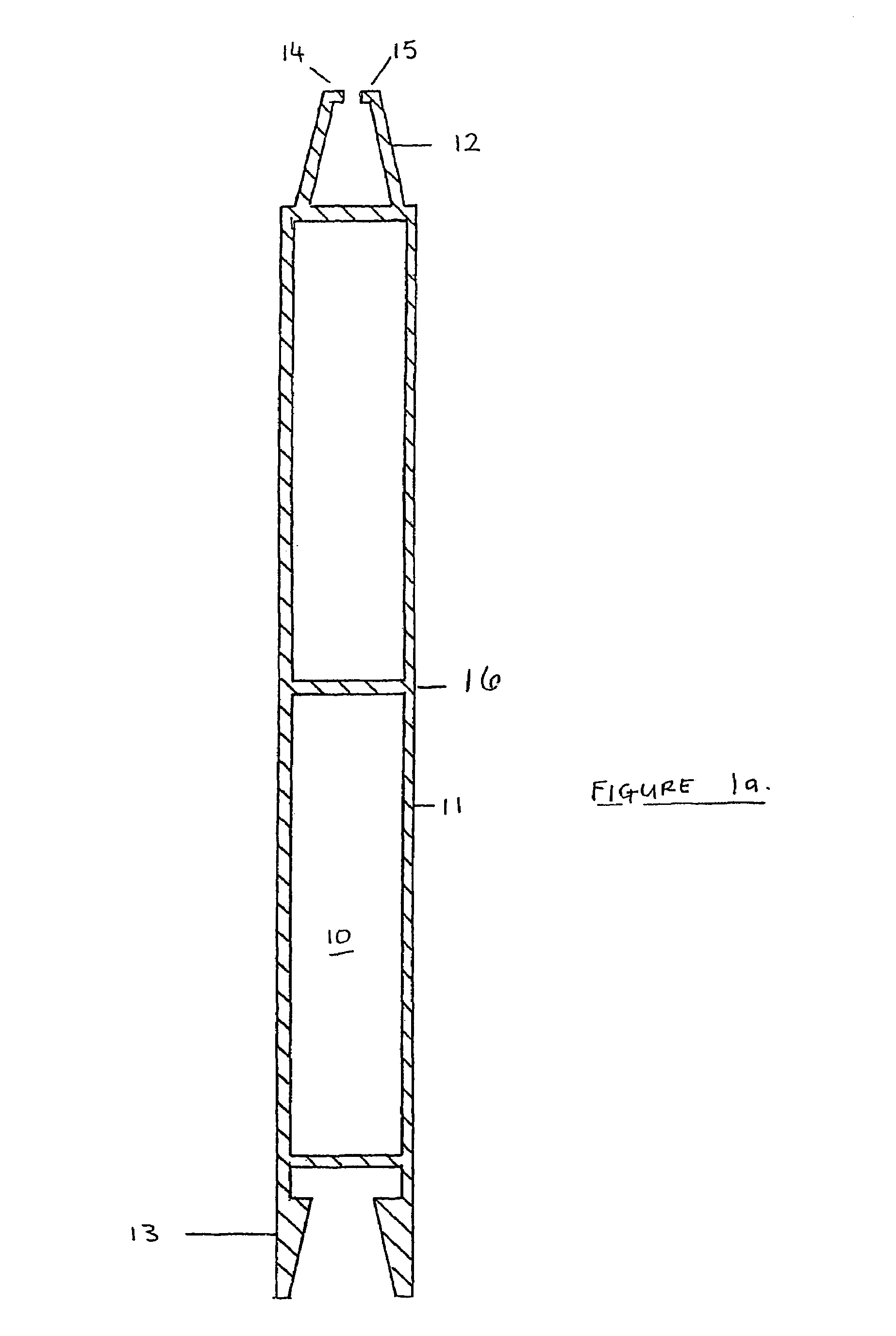
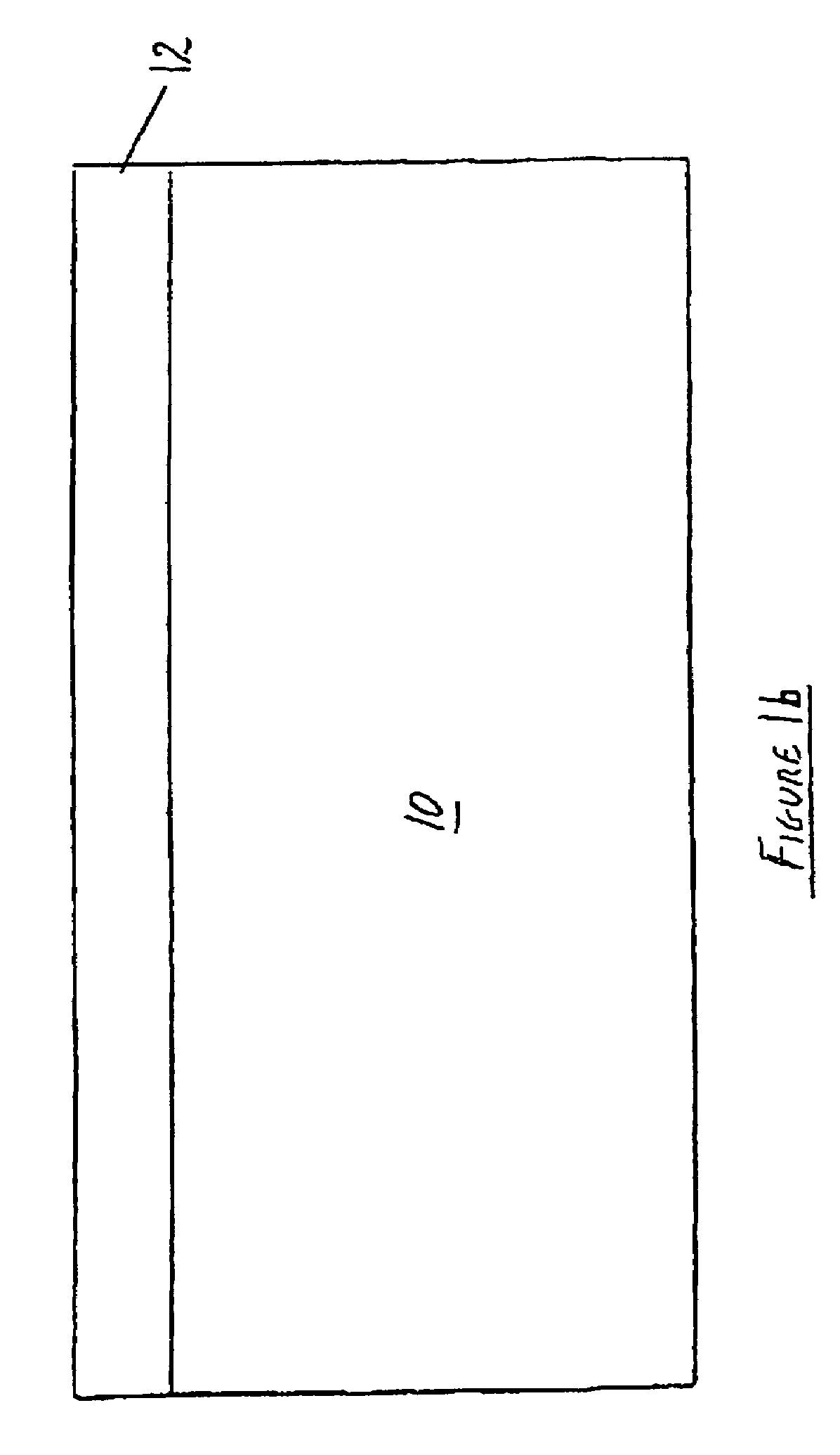
[0043]In FIG. 1, a panel 10 comprises a surface 11, which, in use, faces and engages the flood waters and prevents their entry through an aperture of a building. The panel 10 has an upper panel-engaging portion 12 and a lower panel-engaging portion 13. The upper and the lower panel-engaging portions 12,13 run the length of the panel 10, and in use co-operatively sealingly engage with the corresponding lower and upper portions of further panels 10. The upper panel-engaging portion 12, has two flanges 14,15 extending inwardly. The panel 10 is hollow, a cross-piece 16 providing additional strengthening to the panel.

[0044]The panel 20 of FIG. 2, illustrates a further configuration of a lower panel-engaging portion 21. FIG. 3 illustrates two panels 10 co-operating to form a water-tight seal. Barriers to prevent flood waters from entering through an aperture can thus be built up in height, in accordance with the height of the flood water.

[0045]FIG. 4 illustrates a housing 40 to retain the...


PUM


Abstract

An apparatus to protect an aperture of a building and / or a closure means associated with the aperture from floodwater has a barrier housing (40), which is removably fixable to at least a portion of the periphery of the aperture. The banner housing (40) includes a channel (44) into which a barrier member (10) can slide, forming a seal. A resilient layer (61) is included between the barrier housing (40) and the barrier member (10). The resilient layer (61) can include one or more splines (62). A compression means (90) can be included to urge the housing (40) and the barrier member (10) together to form a seal. Further sealing material, in the form of a member of strips (70), can be included between adjacent barrier members (10). The strips (70) are attached to the in-use upper surface of a barrier member (10), and engage the in-use lower surface of an adjacent barrier member.

Description

FIELD OF THE INVENTION[0001]The present invention concerns an apparatus for use in preventing flood water reaching an entry point such as a door, window or air brick of a building. The apparatus is particularly adapted to be demountable and to be used with existing doorways and windows.BACKGROUND TO THE INVENTION[0002]Floodwaters, particularly from swollen rivers and high tides can cause widespread and costly damage. The damage caused is not only to crops, roadways and other externally located constructions which become at least partially submerged, but also to the interiors of properties such as warehouses or domestic dwellings. The apparent increase in the frequency of floodwater causing such damage has highlighted the costs involved in reparation and that these costs are borne principally by insurance companies or property owners.[0003]The problem of the flooding of domestic dwellings has recently increased, due to changes in government policy regarding where new housing may be l...

Claims


Application Information

Patent Timeline
Patent Type & Authority Patents(United States)
IPC IPC(8): E06B9/06E06B9/02
CPCE06B9/02E06B2009/007
Inventor ABBOTT, STEVEN
Owner FLOODARK
Learn More