One piece slipper holddown device

a technology of slipper and holddown device, which is applied in the direction of reciprocating piston engine, positive displacement liquid engine, etc., can solve the problems of difficult assembling, difficult to retrieve, and the remaining pins may not be able to provide the desired planar support, etc., to achieve easy assembly of the rotating group, reliable product results, and enhanced flexibility of assembly process

Inactive Publication Date: 2009-06-16
SAUER DANFOSS NORDBERG
View PDF5 Cites 4 Cited by
  • Summary
  • Abstract
  • Description
  • Claims
  • Application Information

AI Technical Summary

Benefits of technology

[0013]Before or after inserting the shaft, one end of the pins are inserted into the holes in the cylinder block, their opposite ends being in a fixed relation to each other while being affixed to the ball guide. Thus, the pins are radially constrained in the holes without applying external forces. The flexibility of the assembly process is enhanced. Not only does this apparatus make assembly of the rotating group much easier, a more reliable product results. The pins will not be dislodged and lost in the assembly process.

Problems solved by technology

Another shortcoming of this spring retained pin mechanism is that it is difficult to assemble.
The pins may fall into the cylinder block or rotating group assembly where they are difficult to retrieve.
If one of the pins becomes dislodged or is inadvertently omitted during servicing or assembly, the remaining pins may not be able to provide the desired planar support.
This adds to the cost of production and assembly.
However, the footed pins are much more costly to manufacture than straight pins.
While an improvement over the previously described holddown pins, this device creates other problems.
Specifically, when needing to replace the pin members, the washer is in an inconvenient location around the shaft causing an individual to partially disassemble the hydraulic unit in order to retrieve the washer.

Method used


Image

  • One piece slipper holddown device
  • One piece slipper holddown device
  • One piece slipper holddown device

Examples


Embodiment Construction

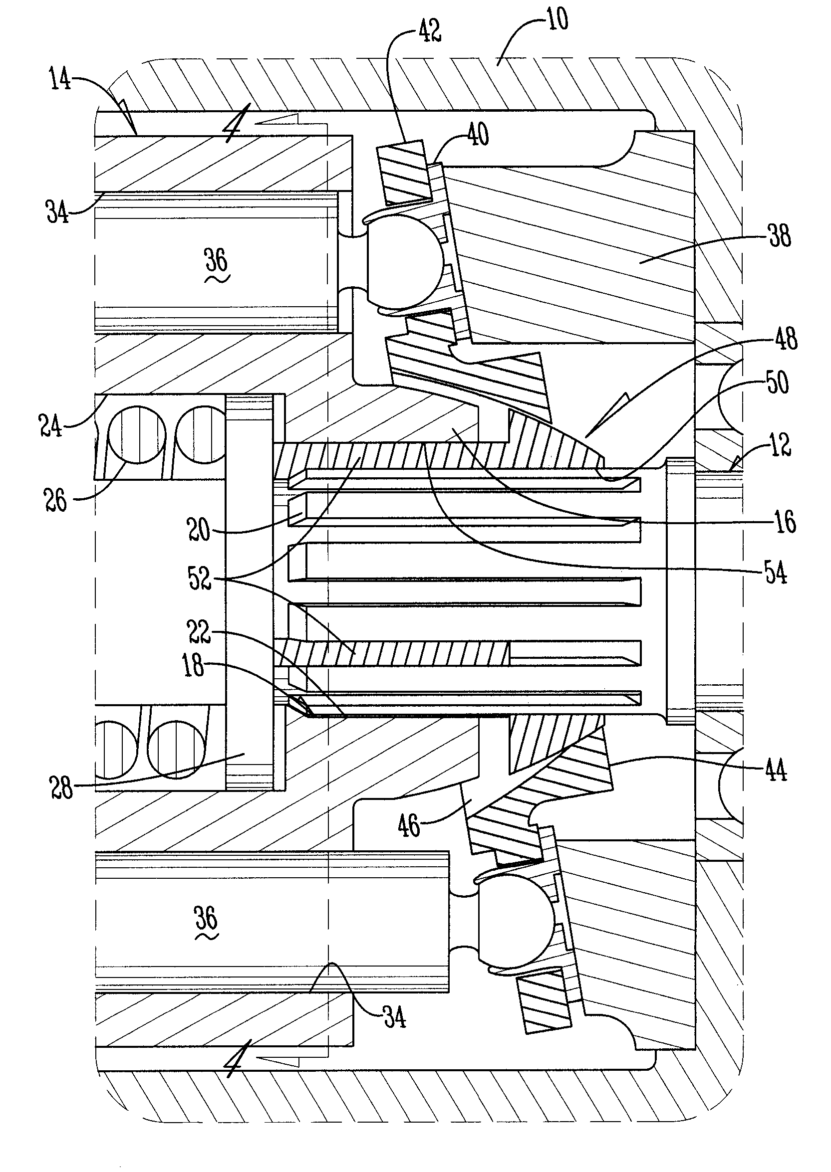
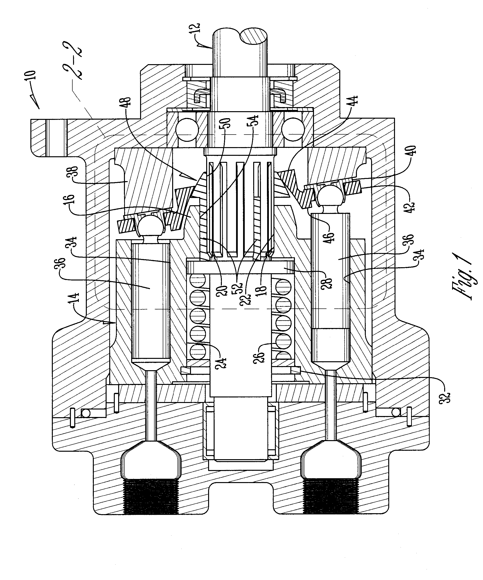
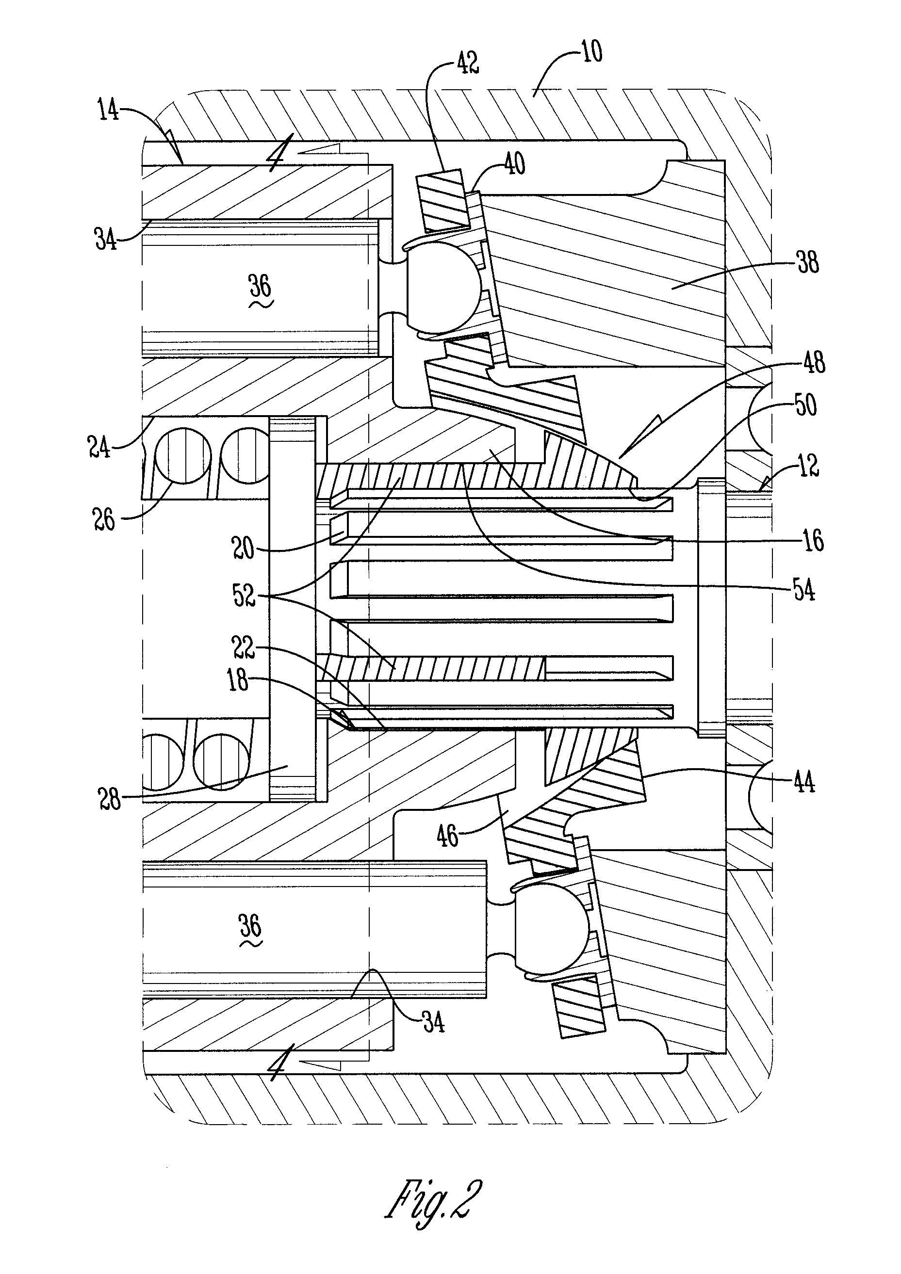
[0020]A hydraulic unit 10 is shown in FIG. 1. For purposes of illustration only, the hydraulic unit 10 is an axial piston open circuit pump. The invention can be adapted to other types of hydraulic units. The pump 10 includes an input shaft 12 which drivingly engages a cylinder block 14. The top of the cylinder block 14 includes a raised hub 16. A centrally located bore 18 (FIGS. 1, 2, 5) extends axially through the cylinder block 14 from top to bottom.

[0021]A series of spaced apart splines 20 are provided on the shaft 12. The splines 20 matingly and drivingly engage a complementary series of spaced internal splines 22 formed on the diameter of the bore 18 of the cylinder block 14, as best seen in FIG. 6. However, other types of shaft / block engagement such as keys fitted to block spring 26 which abuts washer 28 at either end and is held in place by a snap ring 32 conventionally mounted in the bore 24. The shaft 12 extends through the inner diameter of the spring 26.

[0022]As best see...


PUM


Abstract

A holddown pin mechanism for hydraulic power units is a ball guide with a cylindrical flat base having a central opening, a plurality of spaced elongated holddown pins have one end rigidly secured to one side of said ball guide. The pins extend outwardly at right angles from the side of said washer to which they are secured. The holddown pin mechanism is placed in a hydraulic cylinder block having a center bore, with the pins extending into holes in the block. A flat washer on a shaft extending through the block engages the free ends of the pins.

Description

BACKGROUND OF THE INVENTION[0001]The present invention relates to hydraulic power transmission devices, and more specifically to pumps and motors of the axial piston type. The invention further relates to an improved mechanism for retaining pins which hold down the slippers attached respectively to reciprocating pistons.[0002]In conventional axial piston hydraulic units whose inlet or charge pressure is relatively low, a slipper holddown mechanism is generally needed. One type of holddown mechanism utilized in open circuit pumps comprises a plurality of pins mounted in axially extending arcuate grooves spaced around the central bore of the cylinder block. The lower ends of the pins are engaged by a block spring which applies a holddown force that is transmitted to the slippers by the upper ends of the pins.[0003]One shortcoming of the above mechanism is that each groove has a semi-circular cross-section which will only accommodate one-half the diameter of the pin. This allows the pi...

Claims


Application Information

Patent Timeline
Patent Type & Authority Patents(United States)
IPC IPC(8): F01B3/02
CPCF04B1/126F04B1/128F04B1/2078
Inventor BETZ, MICHAEL A.ROBER, DARYL I.KLINKEL, ROBERT
Owner SAUER DANFOSS NORDBERG
Why Eureka
Try Eureka