Mover module and linear motor

A technology of linear motors and components, applied in the direction of electric components, magnetic circuit rotating parts, electrical components, etc., can solve the problems of reducing the repeatability of motor positioning accuracy, damage to the insulation layer, and occupying space for coil windings, so as to ensure performance reliability and The effects of running stability, reducing the difficulty of assembly and manufacturing, and improving the compactness of the structure

Pending Publication Date: 2018-12-07
GREE ELECTRIC APPLIANCES INC
View PDF0 Cites 3 Cited by
  • Summary
  • Abstract
  • Description
  • Claims
  • Application Information

AI Technical Summary

Problems solved by technology

When the linear motor is working, the coil winding generates a lot of heat in a short time, and at the same time, the iron loss of the iron core will also generate a certain amount of heat, which will make the temperature of the entire motor too high. On the one hand, the temperature rise may cause the coil and other wires to exceed their temperature resistance limit. On the other hand, the heat will be transferred to the working platform along with the installation plane, so that it will generate thermal stress and reduce the repeated positioning accuracy of the motor. If it is too high, it will even affect the performance of adjacent mechanisms; in addition, if the temperature rise of the motor iron core teeth is too high, it will also radiate to the motor mover, and the temperature of the magnetic steel will rise accordingly, resulting in a decrease in the performance of the magnetic steel, which will affect the working efficiency of the motor.
Therefore, it is necessary to cool the mover core of the linear motor. The existing cooling methods of the linear motor can be divided into two methods. One is to cool the contact part between the linear motor and the working platform. Targeted cooling has the disadvantage of treating the symptoms but not the root cause. The other is to cool the coil winding part, but most of them adopt the method of external cooling pipeline, which leads to occupying the space of the coil winding, making the corresponding linear motor not compact in size and difficult to assemble. extremely inconvenient

Method used


Image

  • Mover module and linear motor
  • Mover module and linear motor
  • Mover module and linear motor

Examples


Embodiment Construction

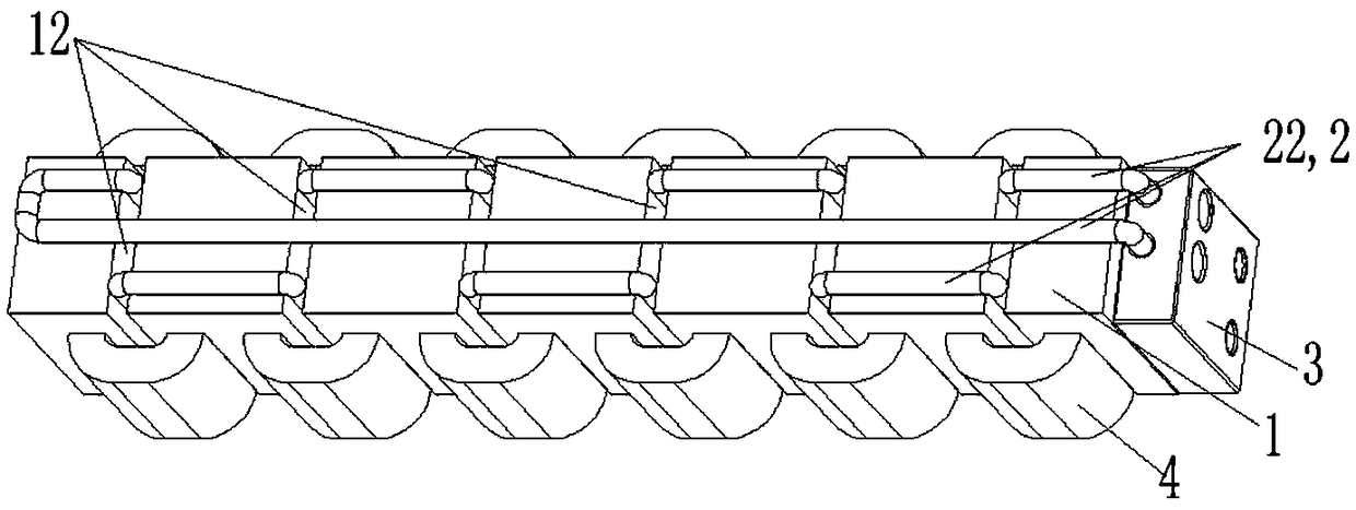
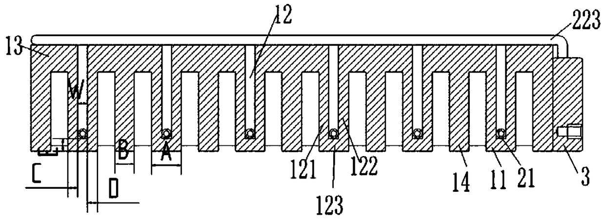
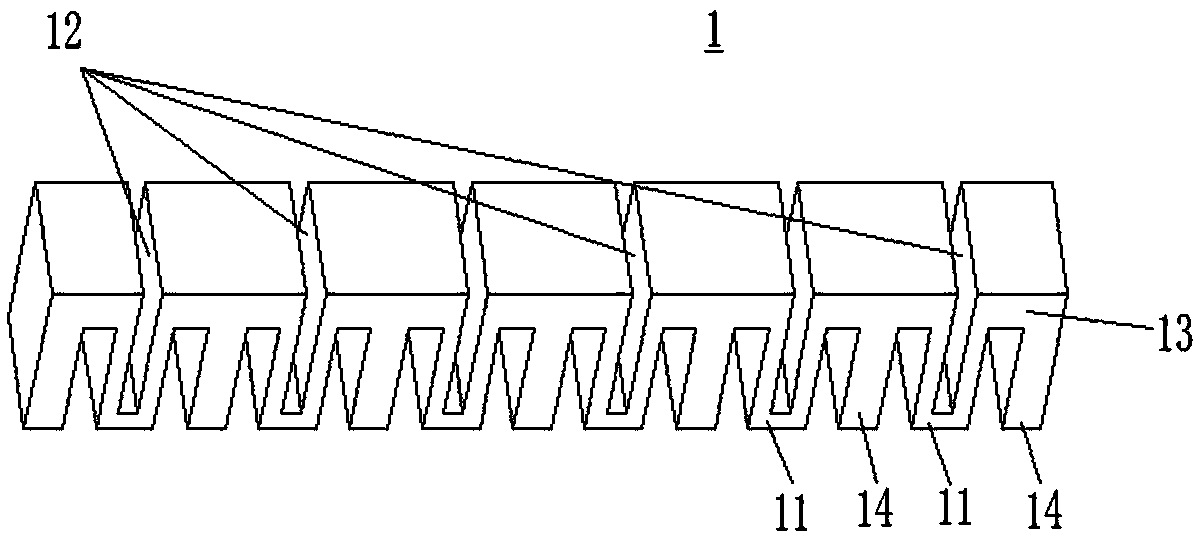
[0025] see Figures 1 to 6 As shown, according to an embodiment of the present invention, a mover assembly is provided, including a mover core 1, the mover core 1 has a first tooth portion 11, and the inner side of the first tooth portion 11 is configured to accommodate The tank 12 also includes a cooling pipeline 2 , and the cooling pipeline 2 includes a tooth pipe section 21 , and the tooth pipe section 21 is installed in the receiving tank 12 . In this technical solution, the cooling pipeline 2 relatively independent from the mover iron core 1 is used to cool the first tooth part 11 of the mover iron core and the coil winding 4 wound outside it in a targeted manner, which can greatly improve the The compact structure of the moving sub-assembly reduces the difficulty of assembly and manufacturing of the moving sub-assembly, effectively controls the temperature rise of the moving sub-assembly and even the linear motor, and is conducive to ensuring the performance reliability ...


PUM


Abstract

The present invention provides a mover module and a linear motor. The mover module comprises a mover iron core, the mover iron core comprises a first tooth portion, a holding cavity is constructed atthe inner side of the first tooth portion, the mover module further comprises a cooling pipeline, and the cooling pipeline comprises a tooth portion pipe section which is arranged in the holding pipe.The mover module and the linear motor can greatly improve the structure compaction of the mover module, can reduce the assembling and manufacturing difficulty of the mover module, can effectively control the temperature rise of the mover module and even the linear motor through targeted cooling of the mover iron core tooth portion and the coil winding and can facilitate ensuring of the performance reliability and the operation stability of the motor.

Description

technical field [0001] The invention belongs to the technical field of motor manufacturing, and in particular relates to a mover assembly and a linear motor. Background technique [0002] Linear motors have the characteristics of high precision, high acceleration, high responsiveness, high thrust, etc., and are widely used in the industrial field, especially in the direction of high-precision machining. When the linear motor is working, the coil winding generates a lot of heat in a short time, and at the same time, the iron loss of the iron core will also generate a certain amount of heat, which will make the temperature of the entire motor too high. On the one hand, the temperature rise may cause the coil and other wires to exceed their temperature resistance limit. On the other hand, the heat will be transferred to the working platform along with the installation plane, so that it will generate thermal stress and reduce the repeated positioning accuracy of the motor. If i...

Claims


Application Information

Patent Timeline
Patent Type & Authority Applications(China)
IPC IPC(8): H02K41/03H02K1/32
CPCH02K41/03H02K1/32
Inventor 谢芳张智超焦雷刘伟健郜曦肖智勇李婉
Owner GREE ELECTRIC APPLIANCES INC
Why Eureka
Try Eureka